Tableau à clics tome 2
Overview
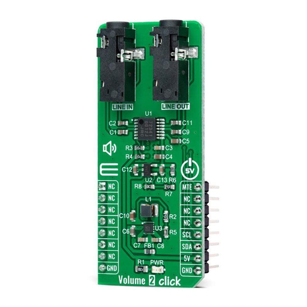
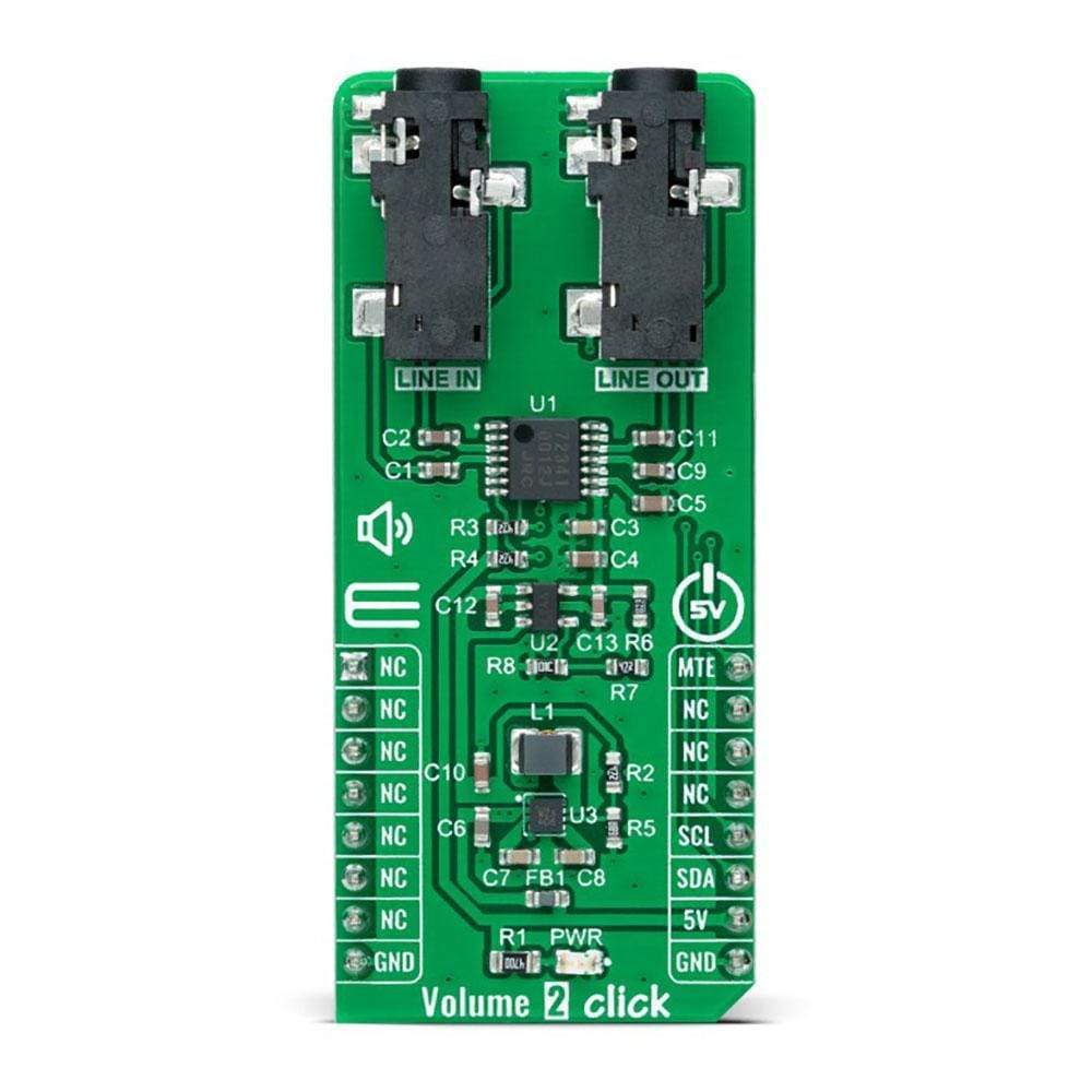
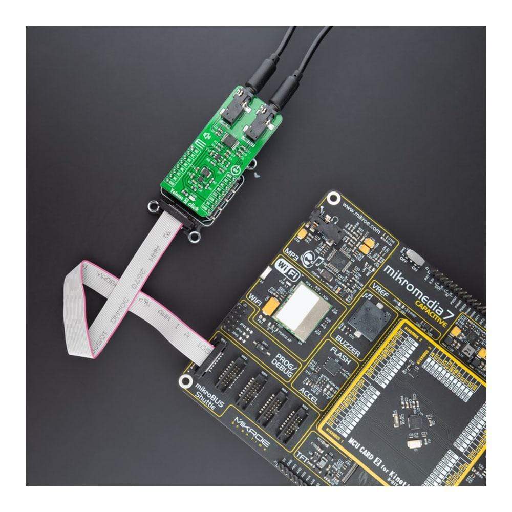
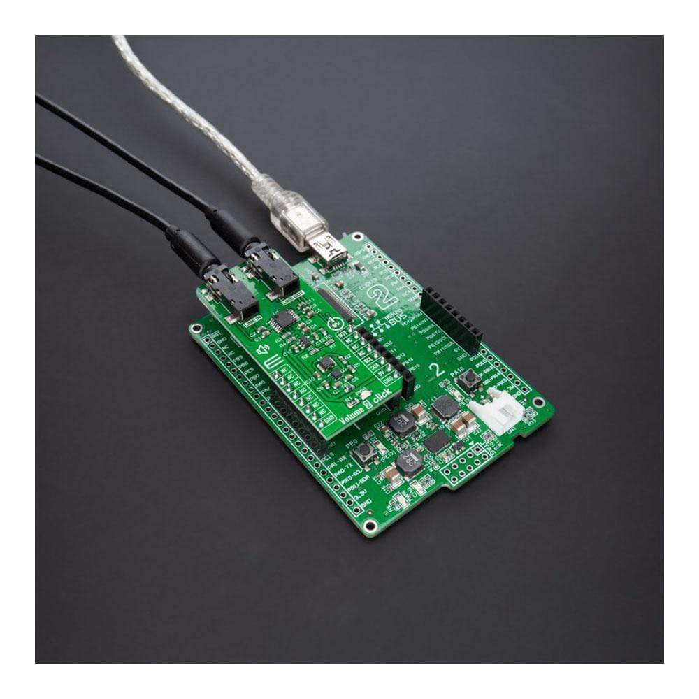
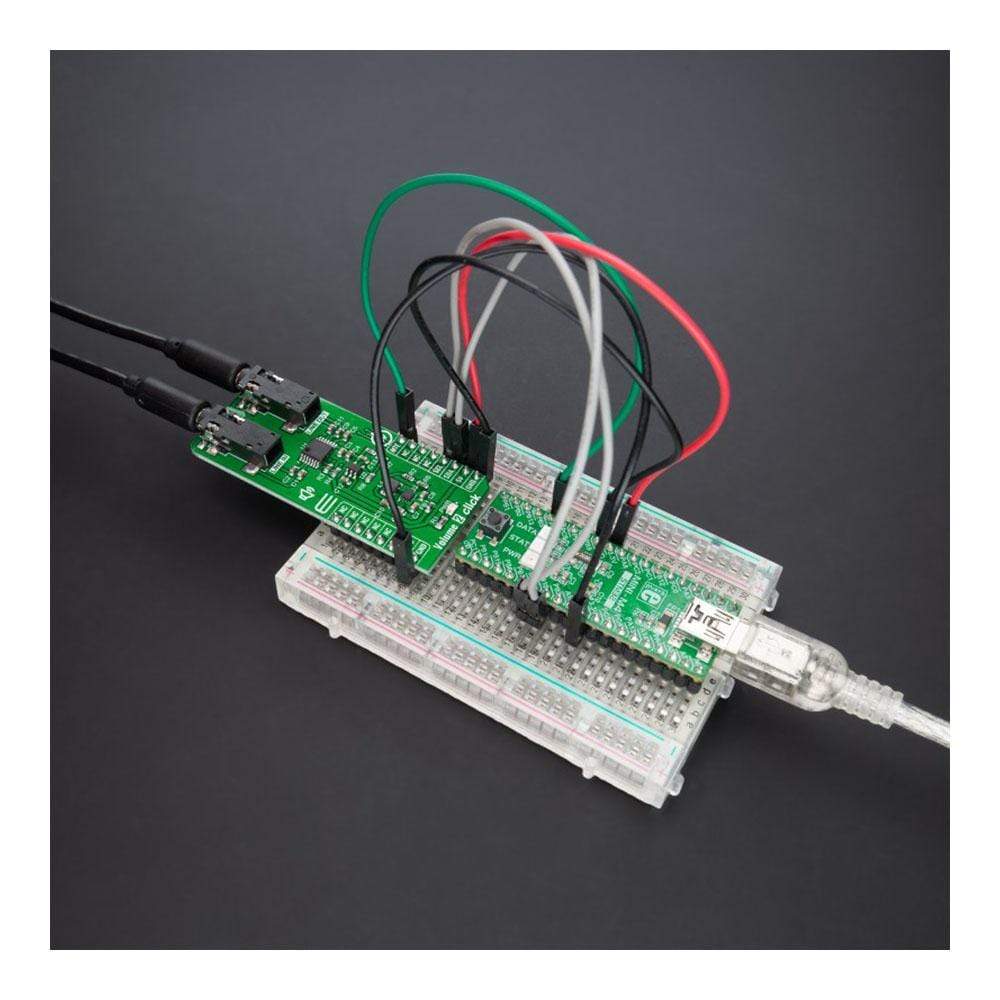
Le Volume 2 Click Board™ est une carte complémentaire compacte qui offre à l'utilisateur un contrôle de volume numérique complet. Cette carte comprend le NJU72341, un circuit intégré de volume électronique configurable I2C à 2 canaux avec contrôle de sourdine externe de NJRC. Il contrôle deux canaux audio indépendants à faible distorsion avec une vaste plage de contrôle du volume de 0 à 95 dB avec un pas de 1 dB offrant une détection de passage par zéro pour protéger le bruit de pop. Il fonctionne avec une interface série I2C simple qui accepte les données 8 bits offrant une faible distorsion et un faible bruit. Ce Click Board™ convient aux systèmes audio stéréo et multicanaux et représente une solution parfaite pour les applications de contrôle du volume audio à distance.
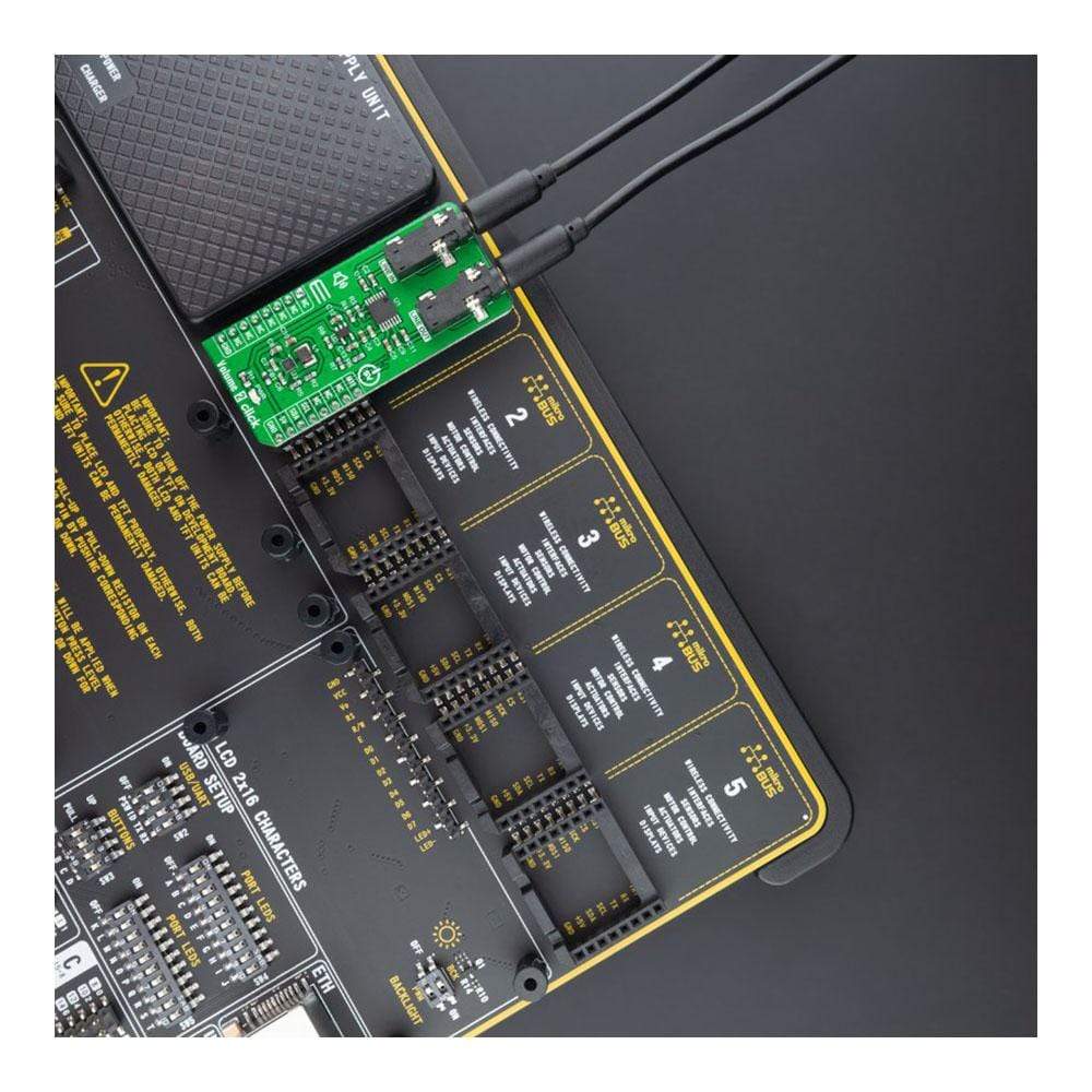
Le Click Board™ du volume 2 est pris en charge par une bibliothèque compatible mikroSDK, qui comprend des fonctions qui simplifient le développement logiciel. Cette Click Board™ est un produit entièrement testé, prêt à être utilisé sur un système équipé du socket mikroBUS™.
How Does The Volume 2 Click Board™ Work?
The Volume 2 Click Board™ as its foundation uses the NJU72341, a 2-channel I2C configurable electronic volume IC with an external mute control from NJRC. The NJU72341 operates as an audio signal processor with many characteristics useful in an audio application, such as low noise typical of 2.0µVrms and low distortion of 0.002%. It controls two independent audio channels with a vast volume control range from 0 to 95dB with 1dB step offering zero-cross detection to protect pop noise. That's why this Click board™ is suitable for stereo and multi-channel audio systems.
The NJU72341 has to receive a specific supply voltage to operate appropriately, in this case, 12V. Unlike the Volume Click, which has symmetrical power supply, in this case, we have only one positive power supply. Bringing just a positive power supply, the noise generated by that power supply will transmit to the output, representing a side effect. For this purpose, Volume 2 Click employs a boost converter unit made by combining MIC5235 and MIC2606, both from Microchip. MIC5235 provides 13V out of 5V from the mikroBUS™ power rail, which then the MIC2606, with a feature of massive noise suppression, lowers it to 12V and then supplies NJU72341 reducing the noise generated at its output.
The Volume 2 Click Board™ communicates with MCU using standard I2C 2-Wire interface, with a clock frequency up to 100kHz in the Standard and 400kHz in the Fast Mode. Also, the user has the option of external mute control configurable through the PWM pin of the mikroBUS™ socket labelled as MTE.
The Volume 2 Click Board™ operates only with a 5V logic voltage level. The board must perform appropriate logic voltage level conversion before use with MCUs with different logic levels. However, the Click board™ comes equipped with a library containing functions and an example code that can be used, as a reference, for further development.
SPECIFICATIONS
Type | Signal Processing |
Applications | Can be used for stereo and multi-channel audio systems and represents a perfect solution for remote audio volume control applications |
On-board modules | NJU72341 - 2-channel I2C configurable electronic volume IC with an external mute control from NJRC |
Key Features | External mute control, low noise, low distortion, I2C configurable, zero cross detection, vast volume control range, and more. |
Interface | I2C |
Compatibility | mikroBUS |
Click board size | L (57.15 x 25.4 mm) |
Input Voltage | 5V |
PINOUT DIAGRAM
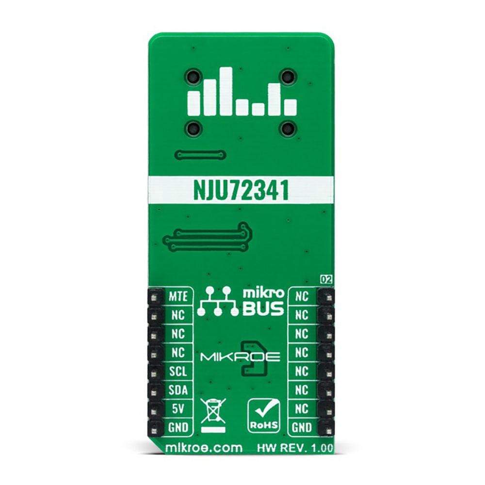
This table shows how the pinout of the Volume 2 Click Board™ corresponds to the pinout on the mikroBUS™ socket (the latter shown in the two middle columns).
Notes | Pin | Pin | Notes | ||||
---|---|---|---|---|---|---|---|
NC | 1 | AN | PWM | 16 | MTE | MUTE Control | |
NC | 2 | RST | INT | 15 | NC | ||
NC | 3 | CS | RX | 14 | NC | ||
NC | 4 | SCK | TX | 13 | NC | ||
NC | 5 | MISO | SCL | 12 | SCL | I2C Clock | |
NC | 6 | MOSI | SDA | 11 | SDA | I2C Data | |
NC | 7 | 3.3V | 5V | 10 | 5V | Power Supply | |
Ground | GND | 8 | GND | GND | 9 | GND | Ground |
ONBOARD SETTINGS AND INDICATORS
Label | Name | Default | Description |
---|---|---|---|
LD1 | PWR | - | Power LED Indicator |
VOLUME 2 CLICK ELECTRICAL SPECIFICATIONS
Description | Min | Typ | Max | Unit |
---|---|---|---|---|
Supply Voltage | - | 5 | - | V |
Volume Control Range | 0 | - | 95 | dB |
Step Size | - | 1 | - | db |
Programmable Gain | 4 | 6 | 8 | db |
Total Harmonic Distortion | - | 0.002 | 0.01 | % |
Operating Temperature Range | -40 | +25 | +85 | deg |
Software Support
We provide a library for the Volume 2 Click Board™ as well as a demo application (example), developed using MikroElektronika compilers. The demo can run on all the main MikroElektronika development boards.
The package can be downloaded/installed directly from NECTO Studio The package Manager (recommended), downloaded from our LibStock™ or found on the mikroE Github account.
Library Description
This library contains the API for the Volume 2 Click Board™ driver.
Key Functions
volume2_cfg_setup
- Config Object Initialization function.volume2_init
- Initialization function.volume2_default_cfg
- Click Default Configuration function.
Example Description
This example shows how the Volume 2 Click Board™ can be used for controlling the audio channels. Thanks to this, a simple audio effect is created by switching volume from right to left and vice versa.
void application_task ( void ) { for ( rising_vol = 0 ; rising_vol < max_atten ; rising_vol++ ) { volume_upd_data.attenuation_ch1 = rising_vol; volume_upd_data.attenuation_ch2 = max_atten - rising_vol; volume2_update_vol_data( &volume2, volume_upd_data ); Delay_ms( 50 ); } Delay_ms( 1000 ); for ( rising_vol = 0 ; rising_vol < max_atten ; rising_vol++ ) { volume_upd_data.attenuation_ch1 = max_atten - rising_vol; volume_upd_data.attenuation_ch2 = rising_vol; volume2_update_vol_data( &volume2, volume_upd_data ); Delay_ms( 50 ); } Delay_ms( 1000 ); }
The full application code, and ready to use projects can be installed directly from NECTO Studio The package Manager (recommended), downloaded from our LibStock™ or found on mikroE Github account.
Other mikroE Libraries used in the example:
- MikroSDK.Board
- MikroSDK.Log
- Click.Volume2
Additional Notes and Information
Depending on the development board you are using, you may need USB UART Click Board™, USB UART 2 Click Board™ or RS232 Click Board™ to connect to your PC, for development systems with no UART to USB interface available on the board. The terminal available in all MikroElektronika compilers, or any other terminal application of your choice, can be used to read the message.
MIKROSDK
The Volume 2 Click Board™ is supported with mikroSDK - MikroElektronika Software Development Kit. To ensure proper operation of mikroSDK compliant Click board™ demo applications, mikroSDK should be downloaded from the LibStock and installed for the compiler you are using.
Frequently Asked Questions
Have a Question?
Be the first to ask a question about this.