Carte Click UART MUX 2
Overview
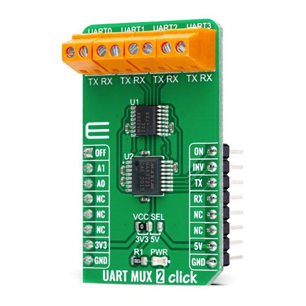
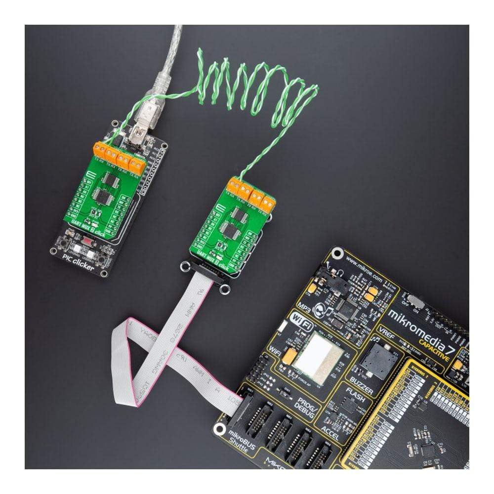
Le Carte Click UART MUX 2™ est une carte complémentaire compacte qui permet une transmission RS232 pseudo-multipoint. Cette carte comprend le MAX399, un multiplexeur analogique CMOS précis qui permet à quatre émetteurs-récepteurs RS-232 distants de partager un seul UART de Maxim Integrated. Il offre des vitesses de commutation rapides avec un temps de transition inférieur à 250 ns et une faible résistance à l'état passant inférieure à 100 Ω tout en conservant la compatibilité d'entrée logique CMOS et une commutation rapide. La sélection des canaux s'effectue via un ensemble de broches GPIO spécifiques et possède des fonctionnalités supplémentaires telles que la fonction ON/OFF manuelle. Cette Click Board™ convient à diverses applications, de l'industrie et de l'instrumentation aux systèmes grand public, de communication, d'acquisition de données et bien d'autres encore.
Le clic UART MUX 2 est pris en charge par une bibliothèque compatible mikroSDK, qui comprend des fonctions qui simplifient le développement logiciel. Cette Click Board™ est un produit entièrement testé, prêt à être utilisé sur un système équipé du socket mikroBUS™.
How Does The UART MUX 2 Click Board™ Work?
The UART MUX 2 Click Board™ as its foundation uses the MAX399, a precise CMOS analogue multiplexer that enables pseudo-multidrop RS232 transmission from Maxim Integrated. This multiplexer allows multiple channels, in this case, four, to share a single UART interface. It offers fast switching speeds with a transition time of less than 250ns and low on-resistance of less than 100Ω while retains CMOS-logic input compatibility and fast switching.
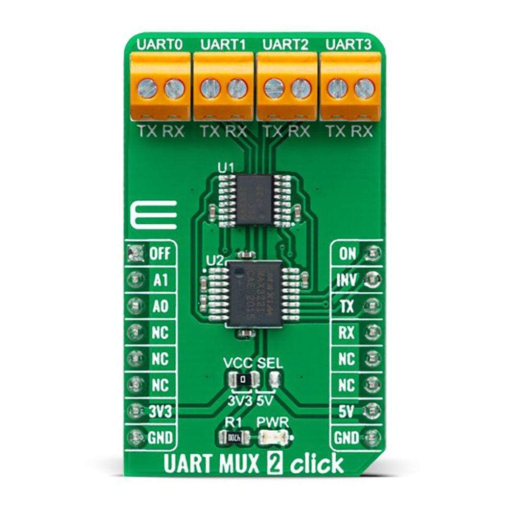
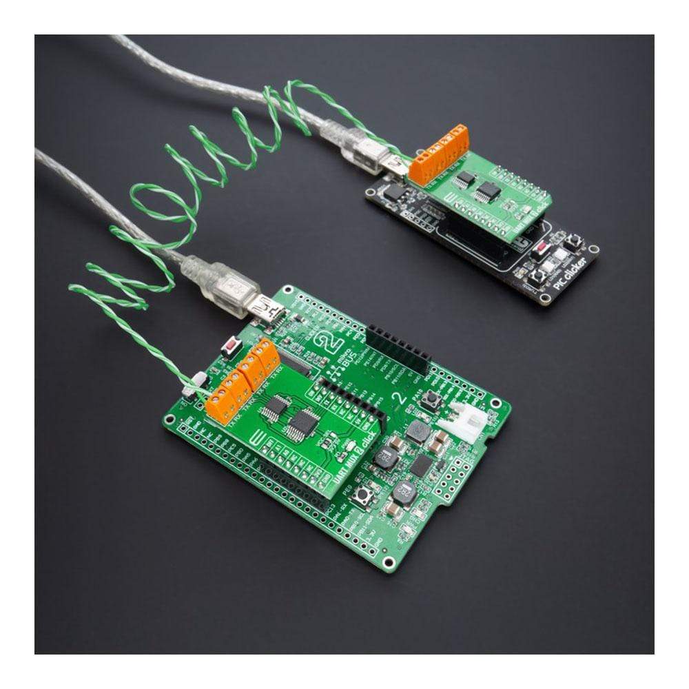
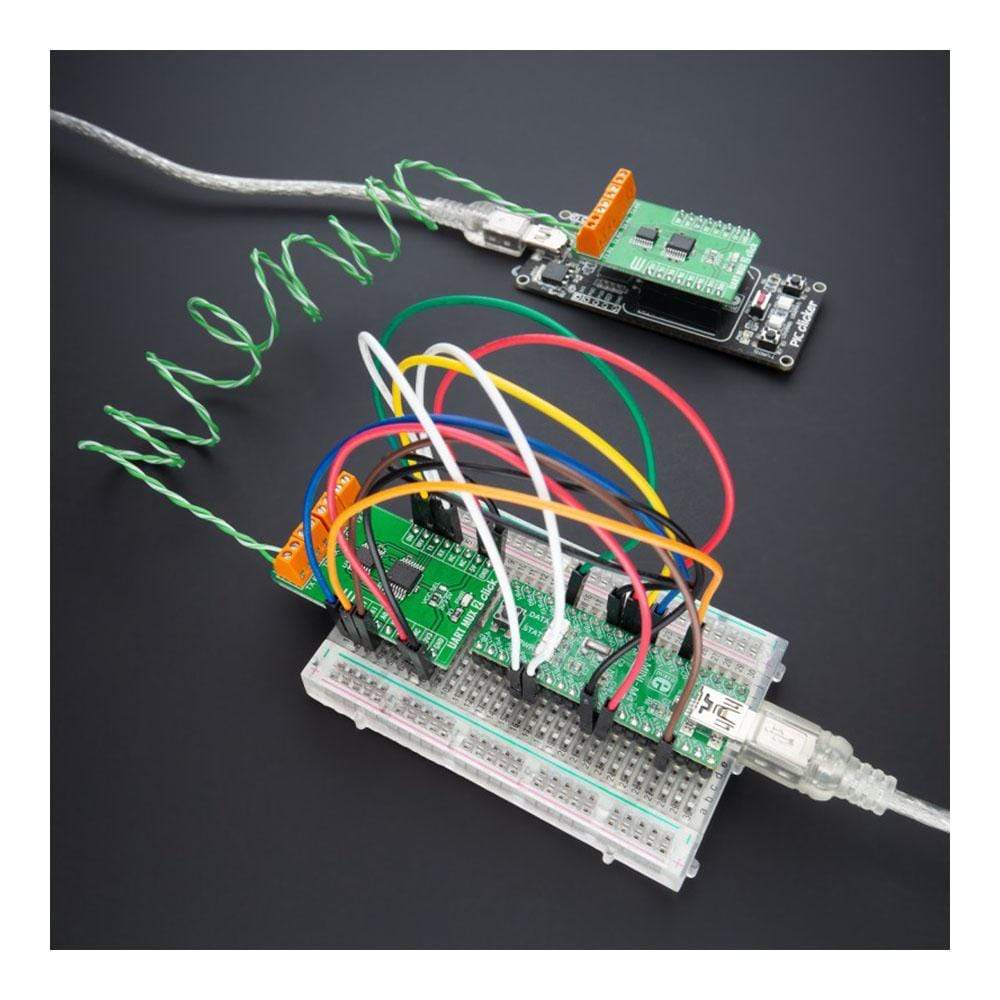
The dual four-to-one multiplexer permits transceiver MAX3221 to form a network with the four remote transceivers connected to terminals labelled as UART0-UART3 located in the upper part of the Click board™. The circuit's supply-voltage range (3V to 5.5V) makes it compatible with 3V and 5V logic. MAX399 receives its power directly from the power terminals of MAX3221, whose ±5.5V outputs come from an internal charge pump. The multiplexer handles rail-to-rail signals, so obtaining its power from MAX3221 ensures that RS232 signals pass directly through, regardless of amplitude.
The UART MUX 2 Click Board™ communicates with MCU through MAX3221 using the UART interface for the data transfer. The MAX3221 can run at data rates up to 250 kbps while maintaining RS232-compliant output levels. Channel selection is performed through a set of specific GPIO pins, labeled as A0 and A1 routed on the CS and RST pins of the mikroBUS™ socket. Selecting its channel 1, for instance, enables MAX3221 to communicate with UART0 without being loaded by UART1 to UART3. Pulldown resistors inside the remote transceivers force the outputs of un-selected receivers to a known state.
In addition to a channel selection, this Click board™ also has an automatic power-down feature that can be disabled when ON and OFF pins are high, routed on the PWM and AN pins of the mikroBUS™ socket. Also, it uses the interrupt pin of the mikroBUS™ labelled as INV as an invalid indicator which makes interfacing with the RS232 simple and easy, indicating whether a valid RS232 signal is present not.
The UART MUX 2 Click Board™ can operate with both 3.3V and 5V logic voltage levels selected via the VCC SEL jumper. This way, it is allowed for both 3.3V and 5V capable MCUs to properly use the UART communication lines. However, the Click board™ comes equipped with a library containing easy-to-use functions and an example code that can be used, as a reference, for further development.
SPECIFICATIONS
Type | RS232 |
Applications | Can be used for a wide range of applications, from industrial and instrumentation to a consumer, communications, data-acquisition systems, and many more. |
On-board modules | MAX399 - precise CMOS analogue multiplexer that enables pseudo-multidrop RS232 transmission from Maxim Integrated MAX3221 - RS232 line driver and receiver from Texas Instruments |
Key Features | Low power consumption, high precision, rail-to-rail signal handling, operates up to 250 kbps, power-down feature, valid RS232 signal indicator, and more. |
Interface | UART |
Compatibility | mikroBUS |
Click board size | M (42.9 x 25.4 mm) |
Input Voltage | 3.3V or 5V |
PINOUT DIAGRAM
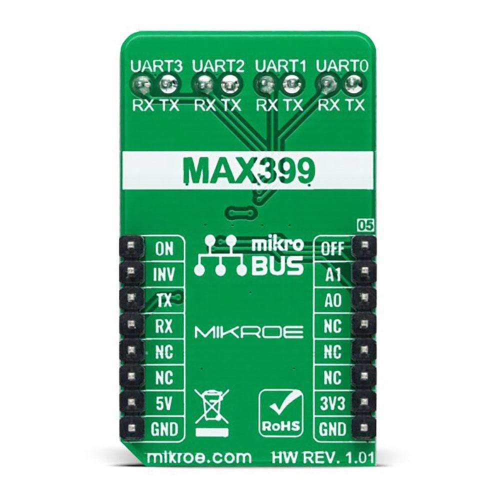
This table shows how the pinout of the UART MUX 2 Click Board™ corresponds to the pinout on the mikroBUS™ socket (the latter shown in the two middle columns).
Notes | Pin | Pin | Notes | ||||
---|---|---|---|---|---|---|---|
Force OFF | OFF | 1 | AN | PWM | 16 | ON | Force ON |
UART Channel Selection Pin 1 |
A1 | 2 | RST | INT | 15 | INV | Valid RS232 Signal Indicator |
UART Channel Selector Pin 0 |
A0 | 3 | CS | RX | 14 | TX | UART TX |
NC | 4 | SCK | TX | 13 | RX | UART RX | |
NC | 5 | MISO | SCL | 12 | NC | ||
NC | 6 | MOSI | SDA | 11 | NC | ||
Power Supply | 3.3V | 7 | 3.3V | 5V | 10 | 5V | Power Supply |
Ground | GND | 8 | GND | GND | 9 | GND | Ground |
ONBOARD SETTINGS AND INDICATORS
Label | Name | Default | Description |
---|---|---|---|
LD1 | PWR | - | Power LED Indicator |
JP1 | VCC SEL | Left | Logic Level Voltage Selection 3V3/5V: Left position 3V3, Right position 5V |
UART MUX 2 CLICK ELECTRICAL SPECIFICATIONS
Description | Min | Typ | Max | Unit |
---|---|---|---|---|
Supply Voltage | 3.3 | +30 | V | |
Data Rate | 150 | 250 | - | kbps |
Operating Temperature Range | 0 | +25 | +70 | °C |
We provide a library for the UART MUX 2 Click Board™ as well as a demo application (example), developed using MikroElektronika compilers. The demo can run on all the main MikroElektronika development boards.
The package can be downloaded/installed directly from NECTO Studio Package Manager(recommended way), downloaded from our LibStock™ or found on the mikroE Github account.
Library Description
This library contains API for the UART MUX 2 Click Board™ driver.
Key Functions
uartmux2_cfg_setup
- Config Object Initialization function.uartmux2_init
- Initialization function.uartmux2_default_cfg
- Click Default Configuration function.
Example Description
This library contains an API for the UART MUX 2 Click Board™ driver. This example transmits/receives and processes data from UART MUX 2 clicks. The library initializes and defines the UART bus drivers to transmit or receive data.
The demo application is composed of two sections :
void application_task ( void ) { #ifdef TRANSIVER for ( uart_ch = UARTMUX2_CHANNEL_0; uart_ch <= UARTMUX2_CHANNEL_3; uart_ch++ ) { uartmux2_set_channel( &uartmux2, uart_ch ); Delay_ms( 100 ); uartmux2_send_data( &uartmux2, demo_message ); log_printf( &logger, " UART%u : ", ( uint16_t ) uart_ch ); for ( uint8_t cnt = 0; cnt < 9; cnt ++ ) { log_printf( &logger, "%c", demo_message[ cnt ] ); Delay_ms( 100 ); } Delay_ms( 2000 ); } log_printf( &logger, "------------------rn" ); Delay_ms( 100 ); #endif #ifdef RECIEVER uartmux2_process( ); if ( app_buf_len > 0 ) { log_printf( &logger, "%s", app_buf ); uartmux2_clear_app_buf( ); } #endif }
The full application code, and ready to use projects can be installed directly from NECTO Studio Package Manager(recommended way), downloaded from our LibStock™ or found on mikroE Github account.
Other mikroE Libraries used in the example:
- MikroSDK.Board
- MikroSDK.Log
- Click.UartMux2
Additional Notes and Information
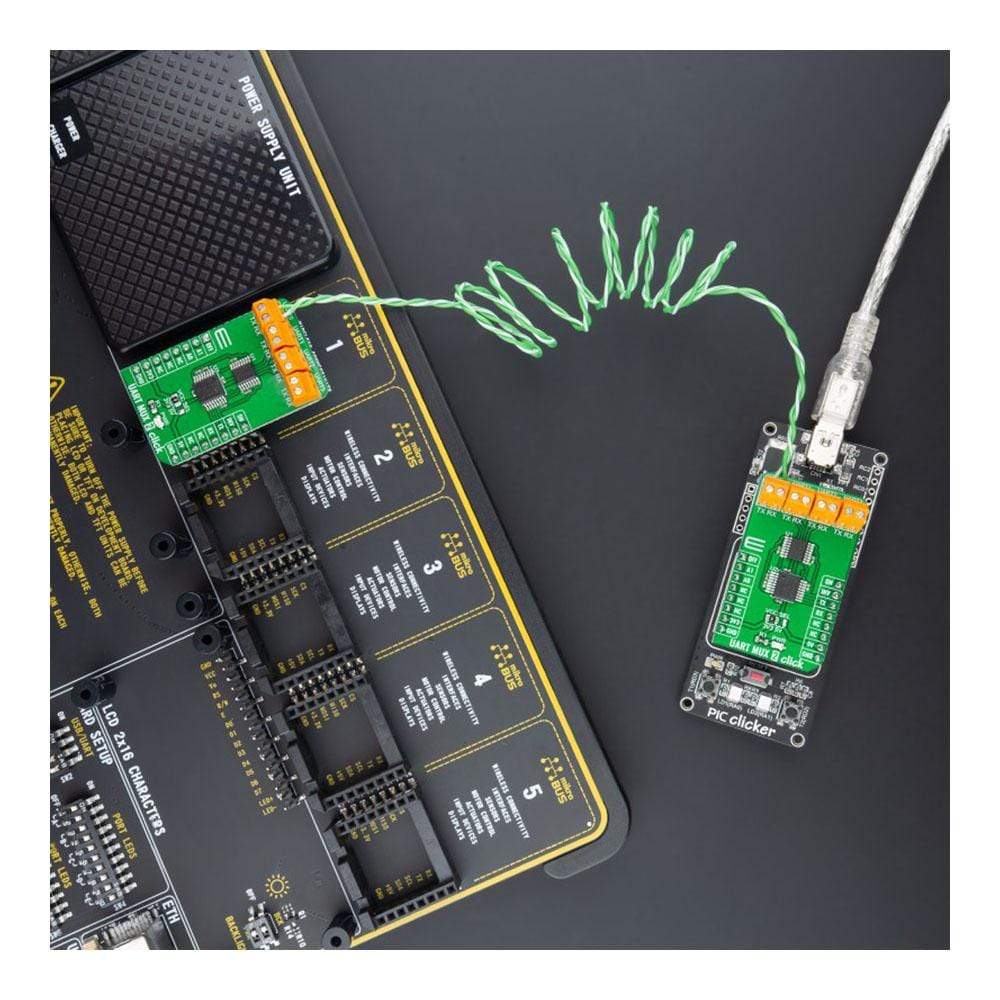
Depending on the development board you are using, you may need a USB UART click, USB UART 2 click or RS232 click to connect to your PC, for development systems with no UART to USB interface available on the board. The terminal available in all MikroElektronika compilers, or any other terminal application of your choice, can be used to read the message.
MIKROSDK
The UART MUX 2 Click Board™ is supported with mikroSDK - MikroElektronika Software Development Kit. To ensure proper operation of mikroSDK compliant Click board™ demo applications, mikroSDK should be downloaded from the LibStock and installed for the compiler you are using.
Frequently Asked Questions
Have a Question?
Be the first to ask a question about this.