


Mikroelektronika d.o.o.
Carte à clic ADC 10
Carte à clic ADC 10
SKU: MIKROE-4488
Impossible de charger la disponibilité du service de retrait


Key Features
Overview
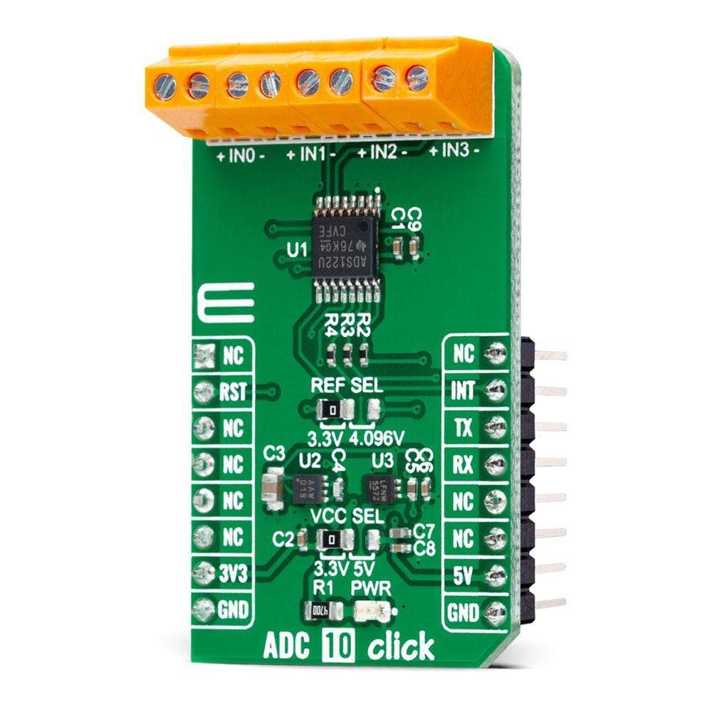
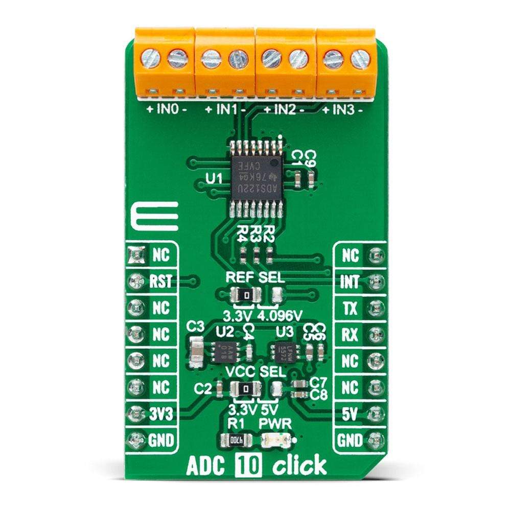
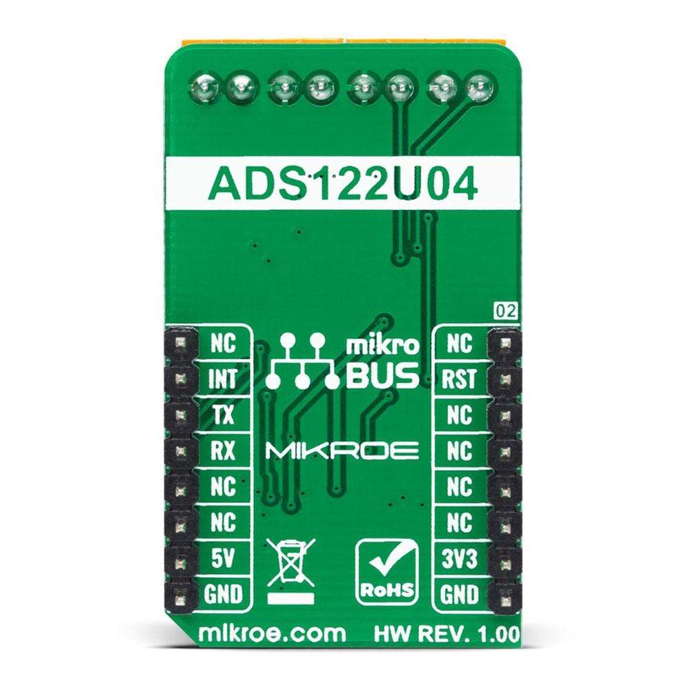
Looking for a high-performance data converter? Look no further than the ADC 10 Click Board™! This compact add-on board features the ADS122U04, a 24-bit precision ΔΣ analogue-to-digital converter with UART compatible interface from Texas Instruments. With its flexible input multiplexer, a programmable gain amplifier, programmable excitation current sources, voltage reference, oscillator, and temperature sensor, the ADS122U04 is capable of conversions at data rates of up to 2000 samples-per-second with single-cycle settling. It's perfect for measuring small sensor signals such as RTDs, thermocouples, thermistors, and resistive bridge sensors.
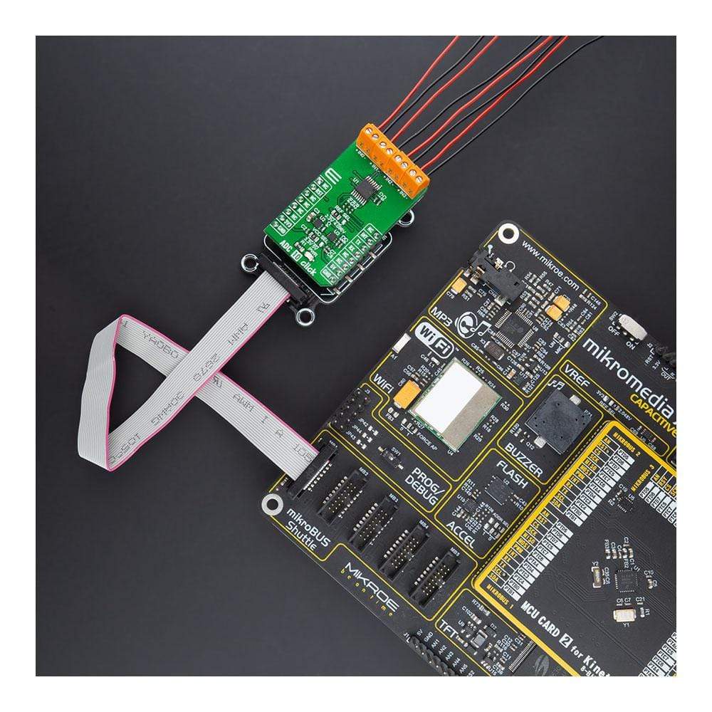
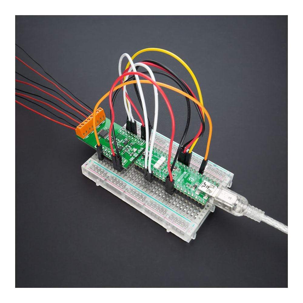
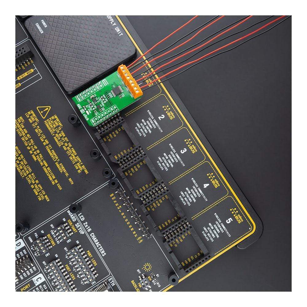
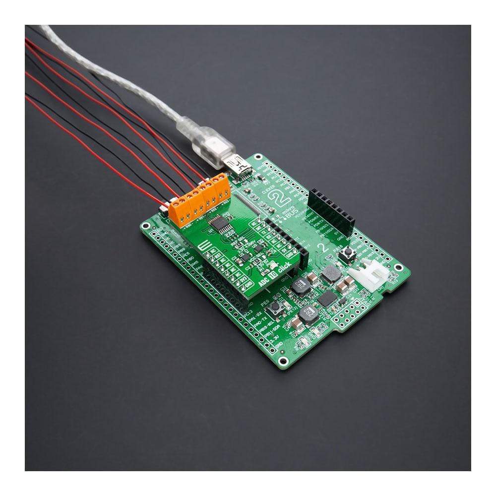
The ADC 10 Click Board™ is easy to use, thanks to its mikroSDK-compliant library and fully tested design. It's ready to be used on any system equipped with a mikroBUS™ socket, making it a convenient and reliable choice for your data conversion needs. Don't miss out on this opportunity to improve your accuracy and performance - get your ADC 10 Click Board™ today!
Downloads
Vous recherchez un convertisseur de données hautes performances ? Ne cherchez pas plus loin que l' ADC 10 Click Board™ ! Cette carte complémentaire compacte comprend l'ADS122U04, un convertisseur analogique-numérique ΔΣ de précision 24 bits avec interface compatible UART de Texas Instruments. Avec son multiplexeur d'entrée flexible, un amplificateur de gain programmable, des sources de courant d'excitation programmables, une référence de tension, un oscillateur et un capteur de température, l'ADS122U04 est capable de conversions à des débits de données allant jusqu'à 2000 échantillons par seconde avec stabilisation à cycle unique. Il est parfait pour mesurer les petits signaux de capteurs tels que les RTD, les thermocouples, les thermistances et les capteurs à pont résistif.
L' ADC 10 Click Board™ est facile à utiliser, grâce à sa bibliothèque compatible mikroSDK et à sa conception entièrement testée. Il est prêt à être utilisé sur n'importe quel système équipé d'un socket mikroBUS™, ce qui en fait un choix pratique et fiable pour vos besoins de conversion de données. Ne manquez pas cette opportunité d'améliorer votre précision et vos performances - obtenez votre ADC 10 Click Board™ dès aujourd'hui !
| General Information | |
|---|---|
Part Number (SKU) |
MIKROE-4488
|
Manufacturer |
|
| Physical and Mechanical | |
Weight |
0.02 kg
|
| Other | |
EAN |
8606027381713
|
Frequently Asked Questions
Have a Question?
Be the first to ask a question about this.