

Mikroelektronika d.o.o.
Carte à clic Opto 5
Carte à clic Opto 5
SKU: MIKROE-4476
Impossible de charger la disponibilité du service de retrait


Overview
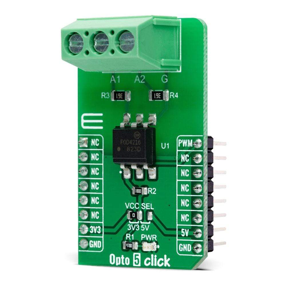
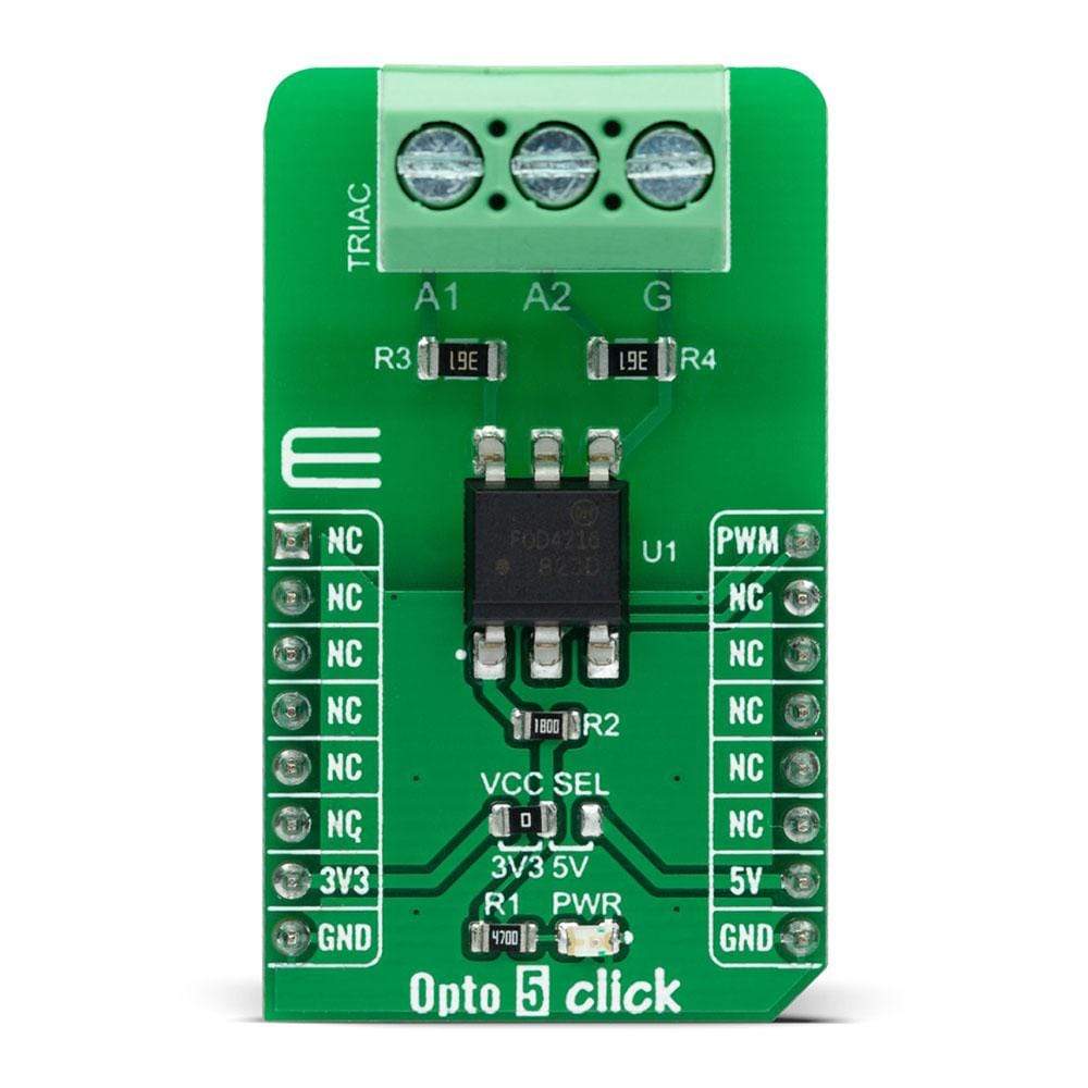
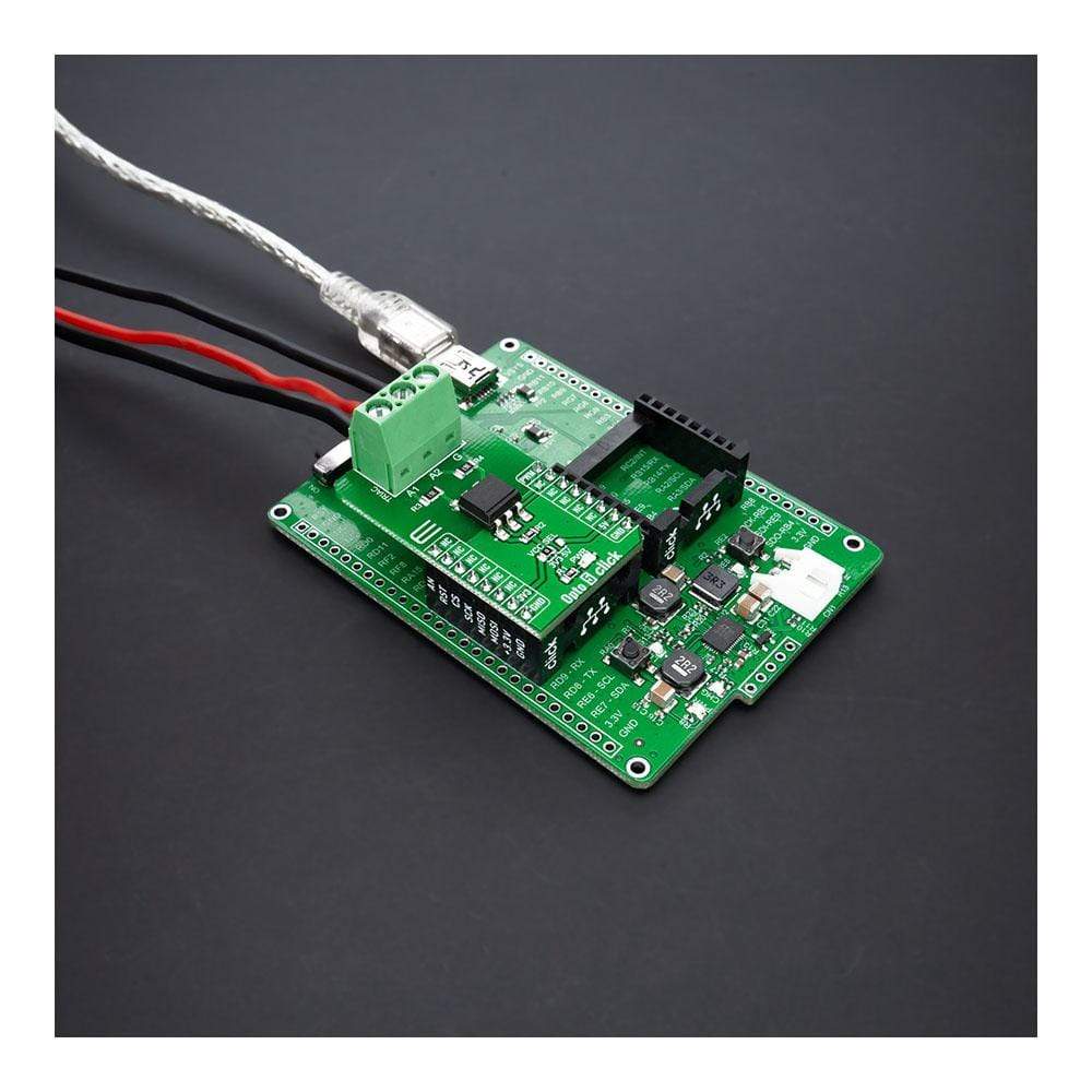
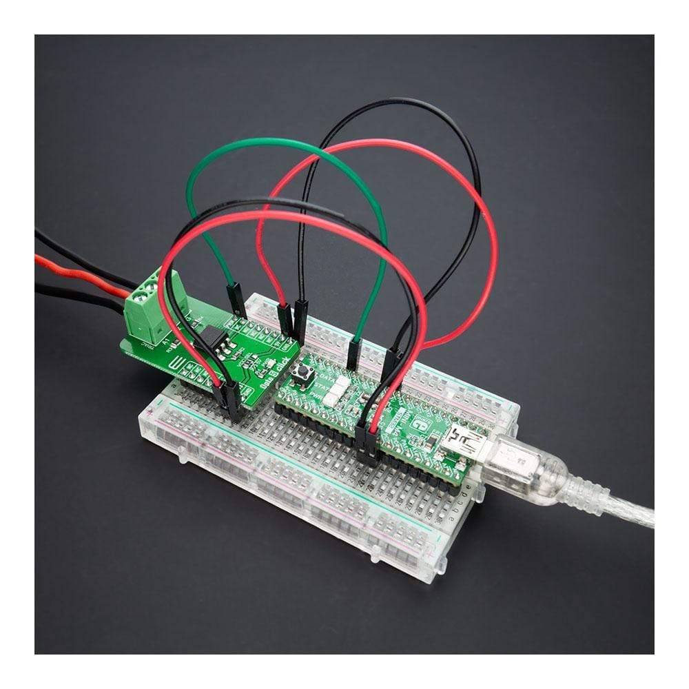
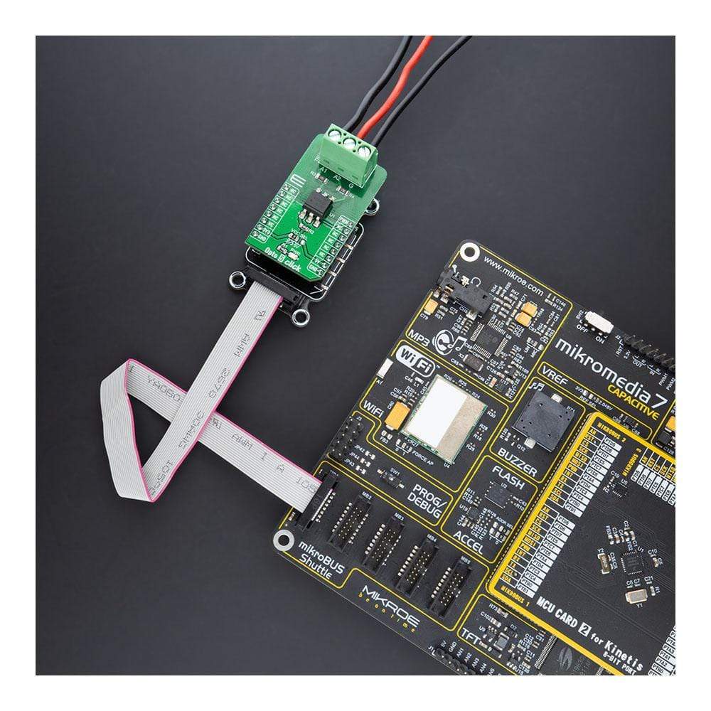
The Opto 5 Click Board™ is a compact add-on board that provides uncomplicated safety isolation from the high voltage. This board features the FOD4216, a random phase snubber-less Triac driver from ON Semiconductor. The FOD4216 consists of an infrared emitting diode coupled to a hybrid random phase triac formed with two inverse parallel SCRs, which creates the triac function capable of driving discrete triacs. It utilizes a high efficiency infrared emitting diode that offers an improved trigger sensitivity. This Click Board™ is suitable for applications like high voltage AC switching where there is a need to protect and electrically isolate two circuits in a switching application.
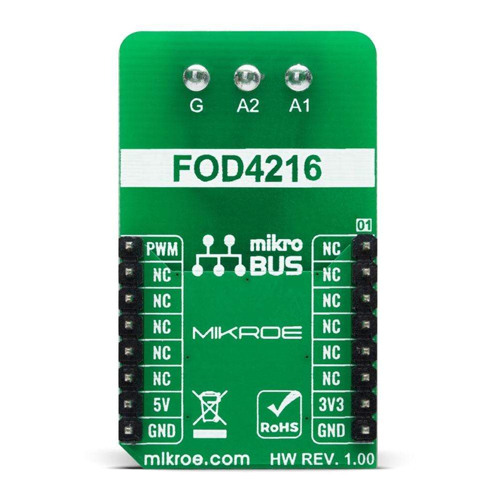
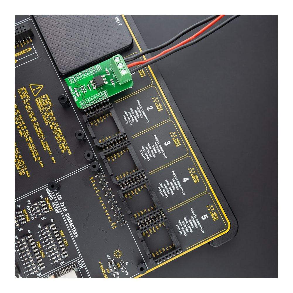
The Opto 5 Click Board™ is supported by a mikroSDK compliant library, which includes functions that simplify software development. This Click Board™ comes as a fully tested product, ready to be used on a system equipped with the mikroBUS™ socket.
Downloads
Le L'Opto 5 Click Board™ est une carte complémentaire compacte qui offre une isolation de sécurité simple contre la haute tension. Cette carte est équipée du FOD4216, un pilote Triac sans amortisseur de phase aléatoire d'ON Semiconductor. Le FOD4216 se compose d'une diode émettrice infrarouge couplée à un triac à phase aléatoire hybride formé de deux SCR parallèles inverses, ce qui crée la fonction triac capable de piloter des triacs discrets. Il utilise une diode émettrice infrarouge à haut rendement qui offre une sensibilité de déclenchement améliorée. Ce Click Board™ convient aux applications telles que la commutation CA haute tension où il est nécessaire de protéger et d'isoler électriquement deux circuits dans une application de commutation.
Le Click Board Opto 5™ est pris en charge par une bibliothèque compatible mikroSDK, qui comprend des fonctions qui simplifient le développement logiciel. Cette Click Board™ est un produit entièrement testé, prêt à être utilisé sur un système équipé du socket mikroBUS™.
| General Information | |
|---|---|
Part Number (SKU) |
MIKROE-4476
|
Manufacturer |
|
| Physical and Mechanical | |
Weight |
0.021 kg
|
| Other | |
EAN |
8606027381690
|
Frequently Asked Questions
Have a Question?
Be the first to ask a question about this.