

Mikroelektronika d.o.o.
Carte EEPROM 5 Click
Carte EEPROM 5 Click
Impossible de charger la disponibilité du service de retrait
Key Features:
- 4 Mbit (512 Ko) d'EEPROM, protection en écriture, plus de 4 millions de cycles d'écriture, conservation des données pendant plus de 40 ans, haute fiabilité, haute densité, etc.
- Basé sur l'EEPROM 5 Click est basé sur le M95M04, la mémoire programmable effaçable électriquement organisée en 524288 x 8 bits accessible via l'interface SPI de STMicroelectronics
- Peut être utilisé pour des données persistantes telles que le code d'application, les tables d'étalonnage et les paramètres utilisateur, ainsi que pour l'enregistrement intensif des données.
- mikroBUS : interface SPI
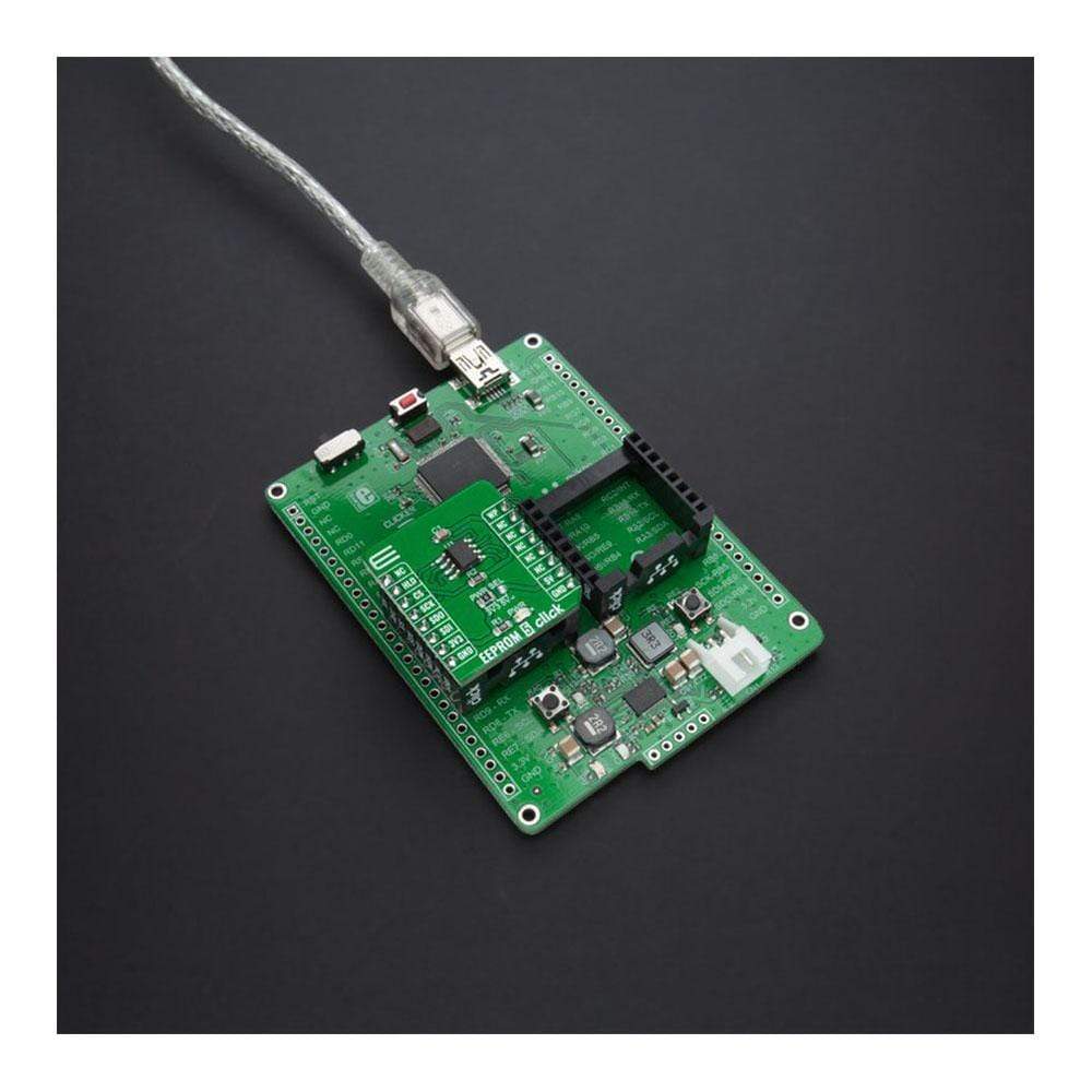
Le Carte EEPROM 5 Click™ est une carte d'extension compacte qui contient la solution de mémoire la plus dense. Cette carte comprend la M95M04, la mémoire programmable effaçable électriquement de 4 Mbits organisée en 524288 x 8 bits accessible via l'interface SPI de STMicroelectronics. La M95M04 combine un stockage de données sans précédent avec une excellente efficacité énergétique. Elle dure un milliard de cycles de lecture-écriture en mémoire complète avec plus de 40 ans de conservation des données. Elle offre également une page d'identification de 512 octets qui peut être utilisée pour stocker des paramètres d'application sensibles qui peuvent être verrouillés de manière permanente en mode lecture seule. Cette Click Board™ convient à une large gamme d'applications dans les contrôles industriels et les infrastructures de communication où un stockage de mémoire accru est nécessaire.
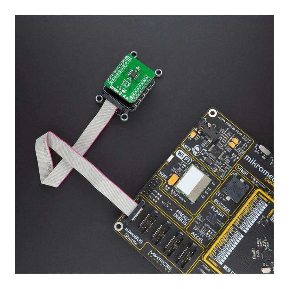
La carte Click Board™ EEPROM 5 est supportée par une bibliothèque compatible mikroSDK, qui comprend des fonctions qui simplifient le développement logiciel. Cette carte Click Board™ est un produit entièrement testé, prêt à être utilisé sur un système équipé du socket mikroBUS™.


How Does The EEPROM 5 Click Board™ Work?
The EEPROM 5 Click Board™ is based on the M95M04, the electrically erasable programmable memory organized as 524288 x 8 bits accessed through the SPI interface from STMicroelectronics. The M95M04 benefit from a wide power supply range of 1.8V to 5.5V, as well as 40 years of data retention, and combines their unprecedented data storage with excellent energy efficiency. It is characterized by high reliability, lasting one billion full-memory read-write cycles capable of writing 512 Bytes in 5ms. With 4Mbit capacity, it allows the capture and storage of more data through the serial SPI bus that enables equipment such as smart meters to intensify data logging for managing grids more effectively and providing more user-friendly billing. This Click board™ also provides high-density non-volatile storage for persistent data such as application code, calibration tables, and user parameters, as well as for intensive data logging.
The EEPROM 5 Click Board™ communicates with MCU using the SPI serial interface that supports the two most common modes, SPI Mode 0 and 3, with a maximum SPI frequency of 10 MHz. In addition to the SPI communication, the EEPROM 5 Click also has two additional pins used for Write Protection and HOLD function routed to the PWM and RST pins of the mikroBUS™ socket.
The HOLD pin, labeled as HLD routed to the RST pin of the mikroBUS™ socket, can be used to pause the serial communication with the M95M04 without having to deselect the device. In Normal operation, the M95M04 is kept selected for the whole duration of the Hold condition. Deselecting the device while it is in the HOLD condition has the effect of resetting the device state. On the other side, the configurable Write Protection function, labelled as WP routed to the PWM pin of the mikroBUS™ socket, allows the user to freeze the size of the area of memory that is protected against Write instructions (as specified by the values in the BP1 and BP0 bits of the STATUS register).
The EEPROM 5 Click Board™ is designed to operate with both 3.3V and 5V logic voltage levels selected via the PWR SEL jumper. It allows for both 3.3V and 5V capable MCUs to use the SPI communication lines properly. However, the Click board™ comes equipped with a library that contains easy to use functions and an example code that can be used, as a reference, for further development.
SPECIFICATIONS
| Type | EEPROM |
| Applications | Can be used with persistent data such as application code, calibration tables, and user parameters, as well as for intensive data logging. |
| On-board modules | The EEPROM 5 Click Board™ is based on the M95M04, the electrically erasable programmable memory organized as 524288 x 8 bits accessed through the SPI interface from STMicroelectronics. |
| Key Features | 4 Mbit (512 Kbytes) of EEPROM, write protection, more than 4 million Write cycles, more than 40-year data retention, high reliability, high density, and more. |
| Interface | SPI |
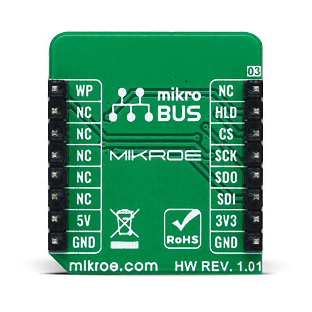
| Compatibility | mikroBUS |
| Click board size | S (28.6 x 25.4 mm) |
| Input Voltage | 3.3V or 5V |
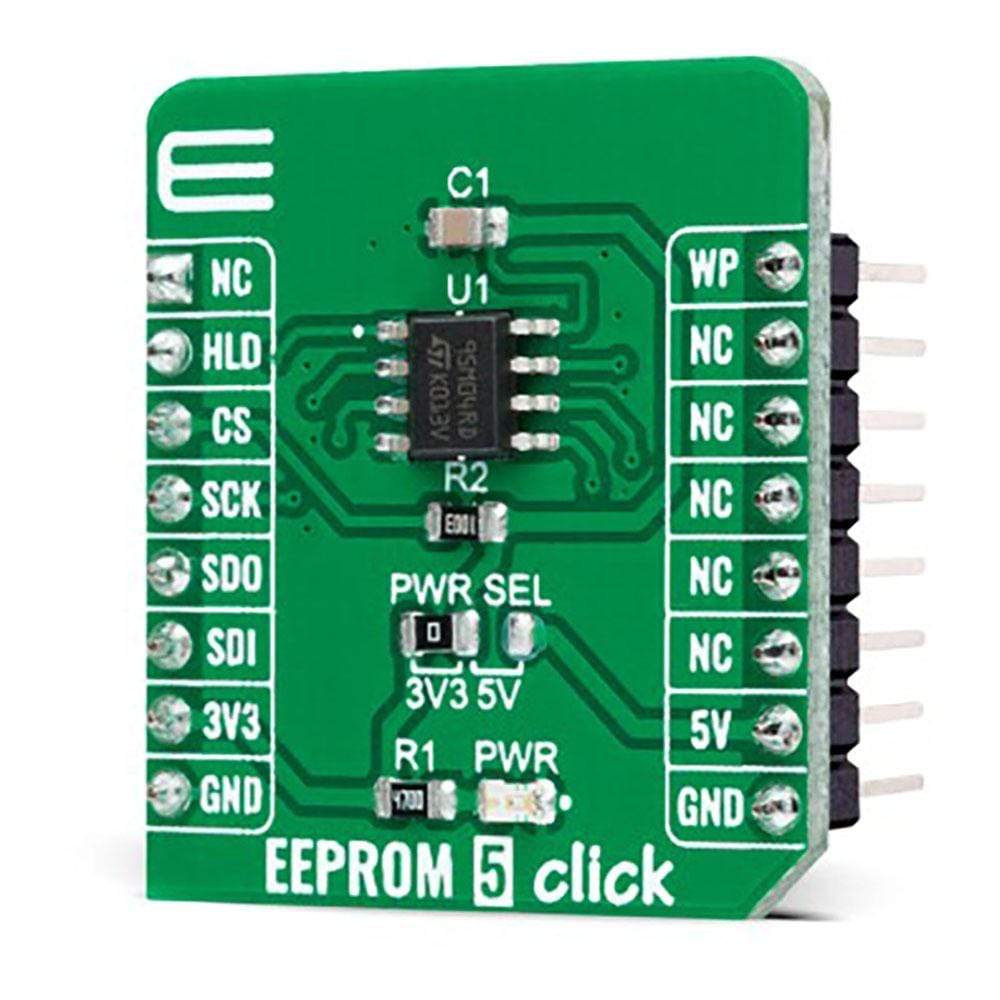
PINOUT DIAGRAM
This table shows how the pinout on the EEPROM 5 Click Board™ corresponds to the pinout on the mikroBUS™ socket (the latter shown in the two middle columns).
| Notes | Pin | Pin | Notes | ||||
|---|---|---|---|---|---|---|---|
| NC | 1 | AN | PWM | 16 | WP | Write Protect | |
| HOLD Function | HLD | 2 | RST | INT | 15 | NC | |
| SPI Chip Select | CS | 3 | CS | RX | 14 | NC | |
| SPI Clock | SCK | 4 | SCK | TX | 13 | NC | |
| SPI Data OUT | SDO | 5 | MISO | SCL | 12 | NC | |
| SPI Data IN | SDI | 6 | MOSI | SDA | 11 | NC | |
| Power Supply | 3.3V | 7 | 3.3V | 5V | 10 | 5V | Power Supply |
| Ground | GND | 8 | GND | GND | 9 | GND | Ground |
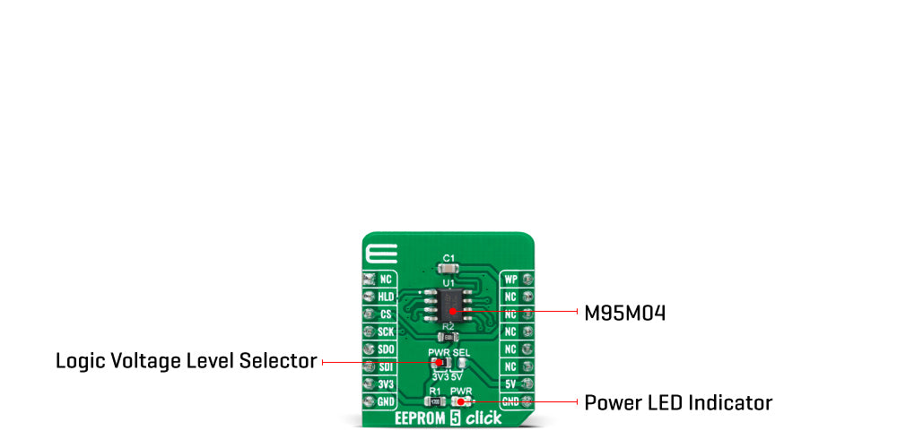
ONBOARD SETTINGS AND INDICATORS
| Label | Name | Default | Description |
|---|---|---|---|
| LD1 | PWR | - | Power LED Indicator |
| JP1 | PWR SEL | Left | Logic Level Voltage Selection 3V3/5V: Left position 3V3, Right position 5V |
EEPROM 5 CLICK ELECTRICAL SPECIFICATIONS
| Description | Min | Typ | Max | Unit |
|---|---|---|---|---|
| Supply Voltage | 1.8 | - | 5.5 | V |
| Maximum Output Current | - | - | 5 | mA |
| Memory Size | - | - | 4096 | kbit |
| EEPROM Write Endurance | - | - | 4000000 | Write Cycles |
| EEPROM Data Retention | 40 | - | - | Years |
| Operating Temperature Range | 40 | - | +85 | °C |
Software Support
We provide a library for the EEPROM 5 Click Board™ on our LibStock page, as well as a demo application (example), developed using MikroElektronika compilers. The demo can run on all the main MikroElektronika development boards.
Library Description
The library covers all the necessary functions to control EEPROM 5 Click board™. The library performs a standard SPI interface communication.
Key Functions
void eeprom5_enable_memory_write ( uint8_t en_wr_mem )- Enable memory write function.oid eeprom5_read_memory ( uint32_t addr, uint8_t *p_rx_data, uint8_t n_bytes )- Read EEPROM memory function.void eeprom5_write_memory ( uint32_t addr, uint8_t *p_tx_data, uint8_t n_bytes )- Write EEPROM memory function.
Example Description
The application is composed of three sections :
- System Initialization - Initializes SPI, sets RST, CS and PWM pin as outputs, begins to write log.
- Application Initialization - Initialization driver enables - SPI, also write log.
- Application Task - (code snippet) This is an example that demonstrates the use of the EEPROM 5 Click board™. In this example, we write and then read data from EEPROM memory. Results are being sent to the Usart Terminal where you can track their changes. All data logs write on USB uart change approximately every 5 sec.
void application_task ( )
{
 eeprom5_enable_memory_write( EEPROM5_WRITE_MEMORY_ENABLE );
 Delay_ms( 10 );
 eeprom5_write_memory( 14, &demo_data[ 0 ], 9 );
 mikrobus_logWrite( " Write data : ", _LOG_TEXT );
 for ( n_cnt = 0; n_cnt < 9; n_cnt++ )
 {
 mikrobus_logWrite( &demo_data[ n_cnt ], _LOG_BYTE );
 }
 mikrobus_logWrite( "- - - - - - - - - - -", _LOG_LINE );
 Delay_ms( 100 );
 mikrobus_logWrite( " Read data : ", _LOG_TEXT );
 eeprom5_read_memory( 14, &read_data[ 0 ], 9 );
 Delay_ms( 1000 );
 for ( n_cnt = 0; n_cnt < 9; n_cnt++ )
 {
 mikrobus_logWrite( &read_data[ n_cnt ], _LOG_BYTE );
 }
 mikrobus_logWrite( "---------------------", _LOG_LINE );
 Delay_ms( 5000 );
}
The full application code, and ready to use projects can be found on our LibStock page.
Other mikroE Libraries used in the example:
- SPI
- UART
- Conversions
Additional Notes and Information
Depending on the development board you are using, you may need a USB UART click, USB UART 2 click or RS232 click to connect to your PC, for development systems with no UART to USB interface available on the board. The terminal available in all MikroElektronika compilers, or any other terminal application of your choice, can be used to read the message.
MIKROSDK
The EEPROM 5 Click Board™ is supported with mikroSDK - MikroElektronika Software Development Kit. To ensure proper operation of mikroSDK compliant Click board™ demo applications, mikroSDK should be downloaded from the LibStock and installed for the compiler you are using.
Carte EEPROM 5 Click
Frequently Asked Questions
Have a Question?
Be the first to ask a question about this.