


Mikroelektronika d.o.o.
Tableau à clic Buzz 3
Tableau à clic Buzz 3
SKU: MIKROE-4390
Impossible de charger la disponibilité du service de retrait


Overview
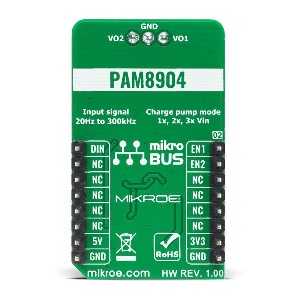
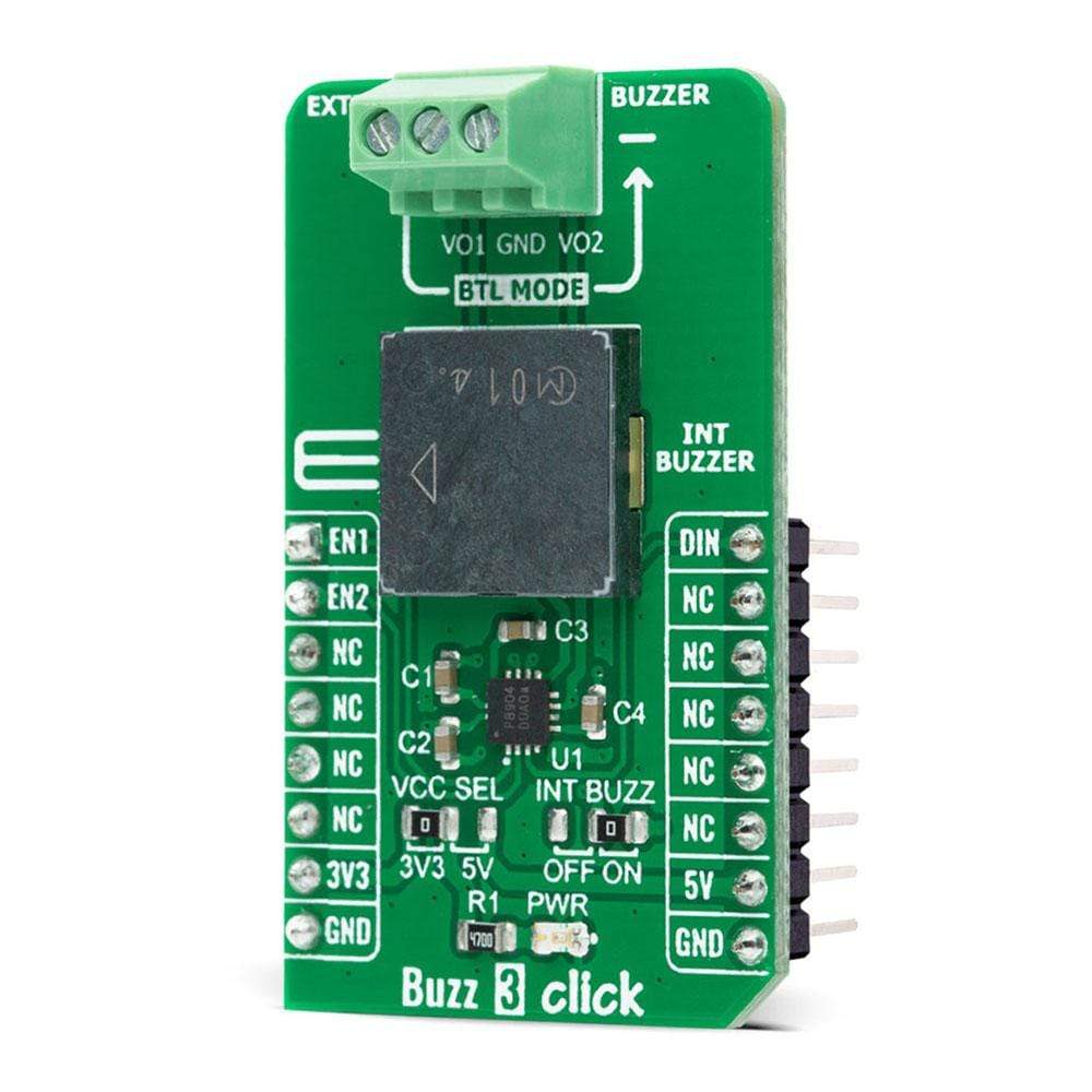
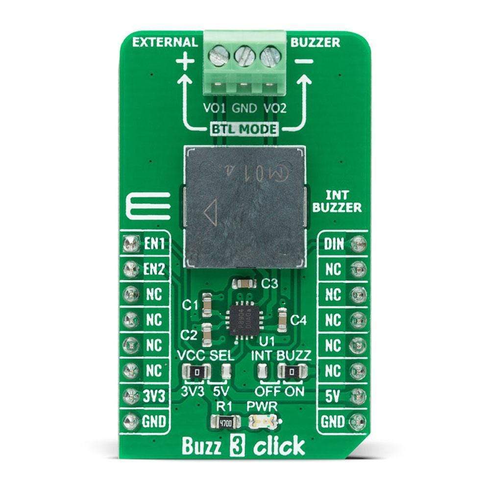
The Buzz 3 Click Board™ is a compact add-on board that contains a sounder driver that produces higher volume with a lower current. This board features the PAM8904, a piezo-sounder driver with an integrated Multi-Mode charge pump boost converter from Diodes Incorporated. With its wide input signal range of 20Hz to 300kHz, the PAM8904 can drive a sounder load of up to 15nF, providing a 9V output. It enables the selection of three different piezo sound pressure levels, keeps current consumption low, and extends battery life by employing built-in automatic shutdown and wake-up functions. This Click Board™ is suitable for a variety of battery-powered applications, including medical systems, alarm clocks, home appliances, and security devices.
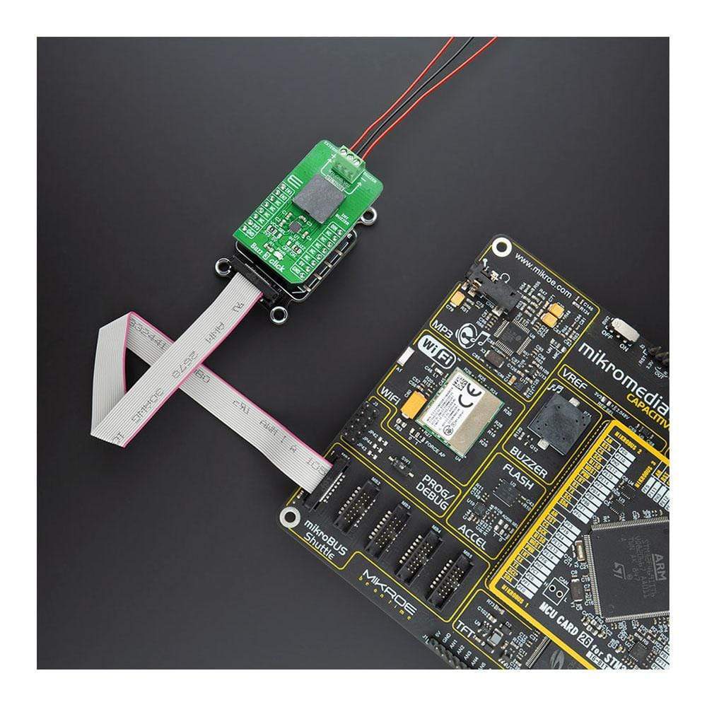
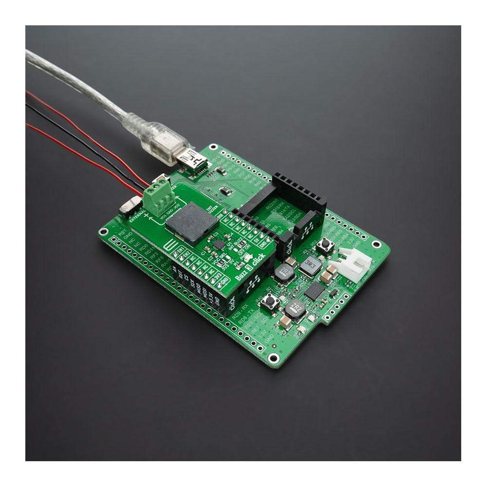
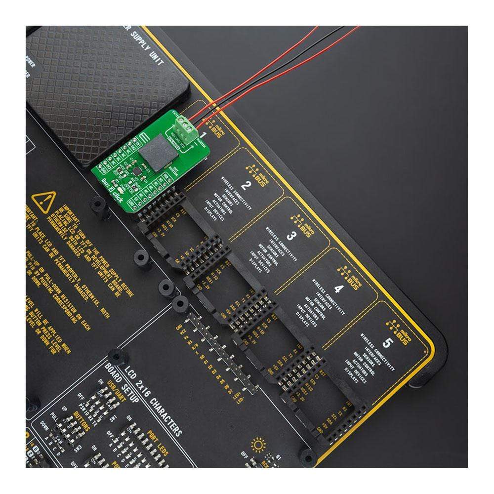
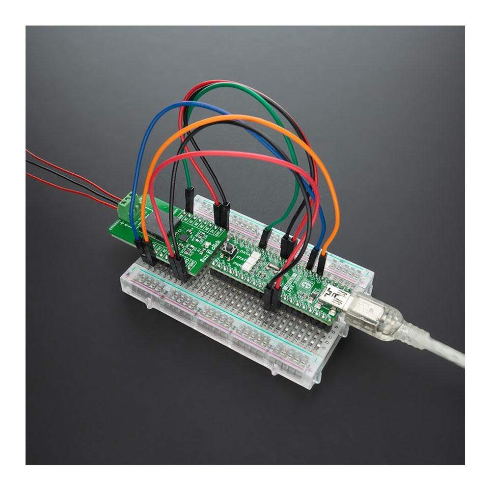
The Buzz 3 Click Board™ is supported by a mikroSDK compliant library, which includes functions that simplify software development. This Click Board™ comes as a fully tested product, ready to be used on a system equipped with the mikroBUS™ socket.
Downloads
Le Buzz 3 Click Board™ est une carte complémentaire compacte qui contient un pilote de sondeur qui produit un volume plus élevé avec un courant plus faible. Cette carte comprend le PAM8904, un pilote de sondeur piézoélectrique avec un convertisseur de suralimentation à pompe de charge multimode intégré de Diodes Incorporated. Avec sa large plage de signaux d'entrée de 20 Hz à 300 kHz, le PAM8904 peut piloter une charge de sondeur jusqu'à 15 nF, fournissant une sortie de 9 V. Il permet de sélectionner trois niveaux de pression sonore piézoélectrique différents, maintient la consommation de courant à un niveau bas et prolonge la durée de vie de la batterie en utilisant des fonctions d'arrêt et de réveil automatiques intégrées. Ce Click Board™ convient à une variété d'applications alimentées par batterie, notamment les systèmes médicaux, les réveils, les appareils électroménagers et les dispositifs de sécurité.
Le Buzz 3 Click Board™ est pris en charge par une bibliothèque compatible mikroSDK, qui comprend des fonctions qui simplifient le développement logiciel. Ce Click Board™ est un produit entièrement testé, prêt à être utilisé sur un système équipé du socket mikroBUS™.
| General Information | |
|---|---|
Part Number (SKU) |
MIKROE-4390
|
Manufacturer |
|
| Physical and Mechanical | |
Weight |
0.018 kg
|
| Other | |
EAN |
8606027381232
|
Frequently Asked Questions
Have a Question?
Be the first to ask a question about this.