


Mikroelektronika d.o.o.
Tableau de clic de limite de courant
Tableau de clic de limite de courant
SKU: MIKROE-4271
Impossible de charger la disponibilité du service de retrait

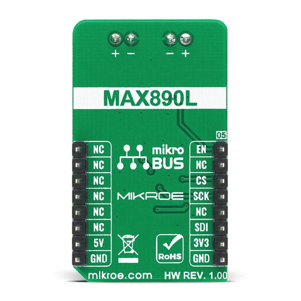


Overview
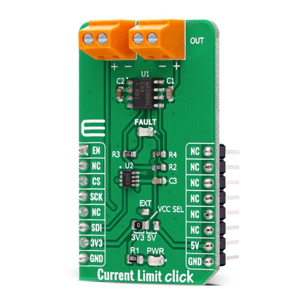
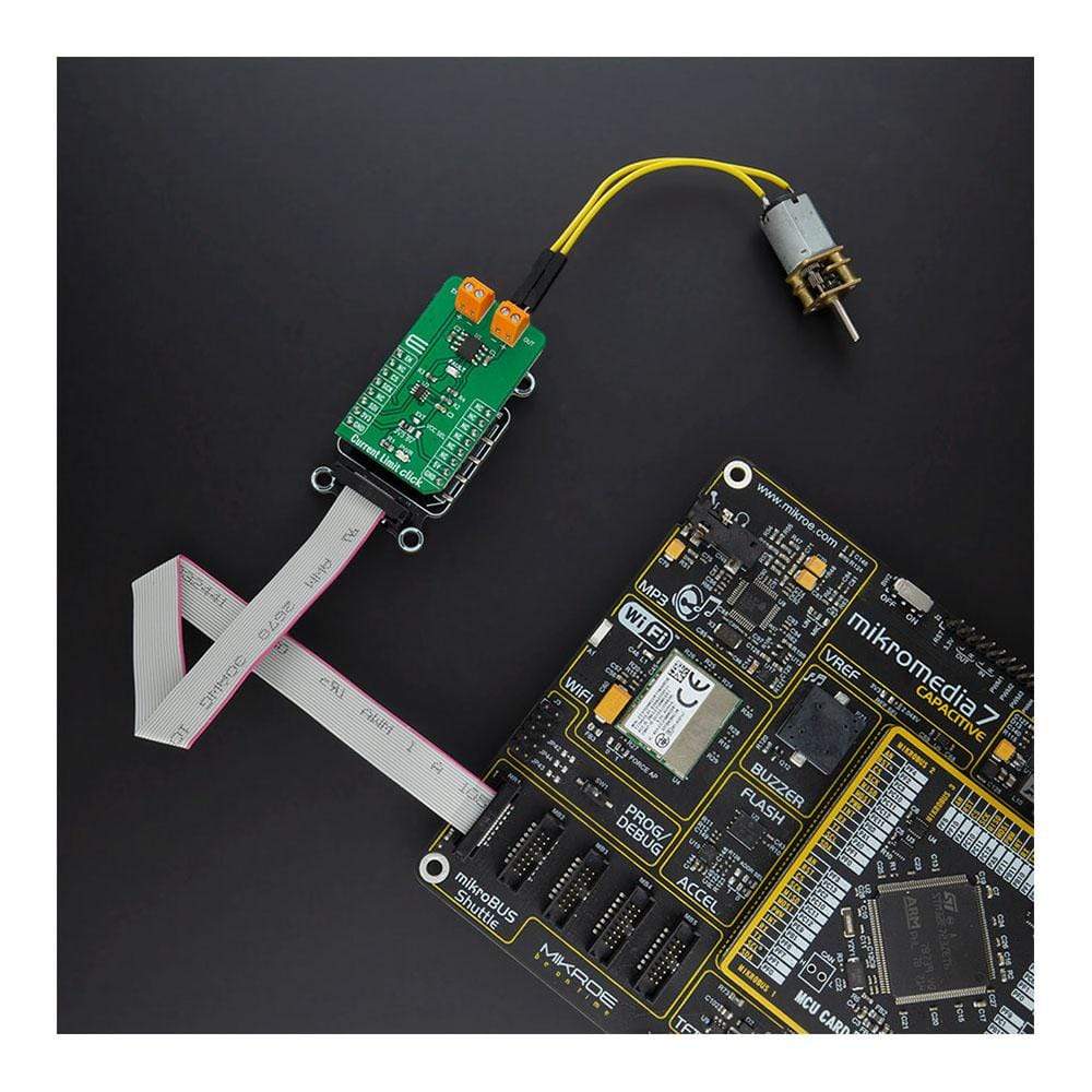
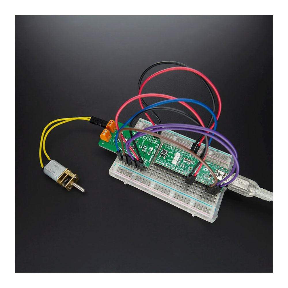
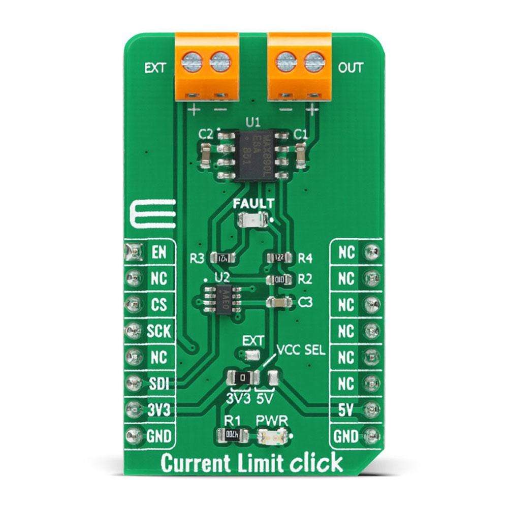
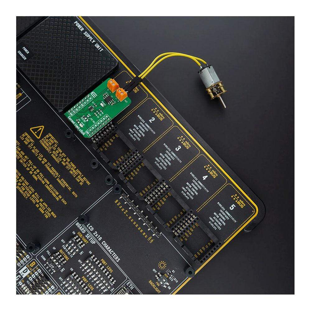
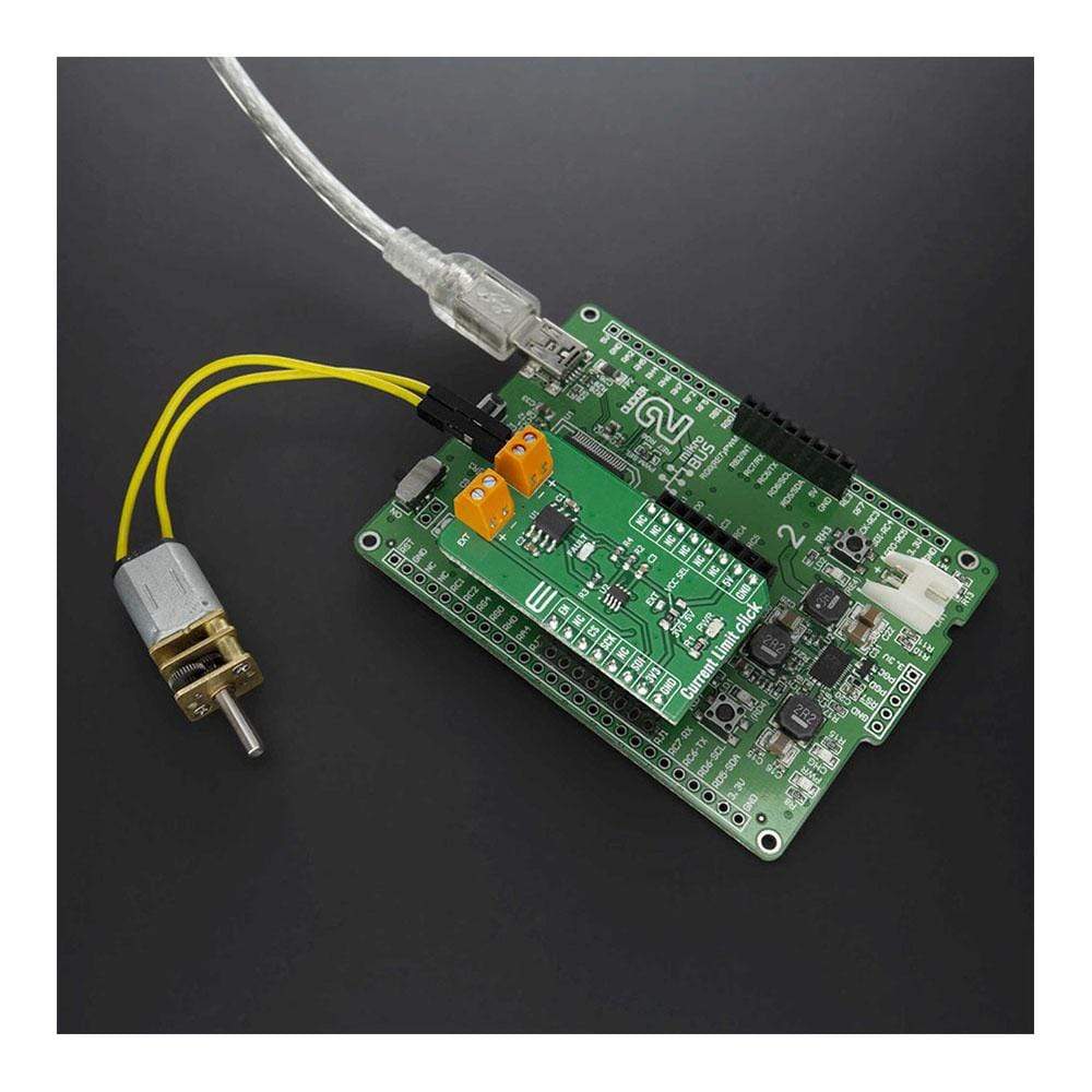
The Current Limit Click Board™ is a compact add-on board that contains a low-voltage, P-channel MOSFET power switch intended for high-side load switching applications. This board features the MAX890L, a low-resistance power switch with an adjustable, accurate current limit system, and thermal shutdown from Maxim Integrated. Its internal current-limiting circuitry protects the input supply against overload, while thermal protection limits power dissipation. The maximum current limit is 1.2A and can be programmed through a digital potentiometer MAX5401. The quiescent supply current has a low value of 10μA in the active state, while in its off state the supply current decreases to 0.1μA. This Click Board™ is suitable for applications in some portable equipment, access bus slots, or with power supplies, protecting them in cases of a short circuit or other overload conditions.
The Current Limit Click Board™ is supported by a mikroSDK compliant library, which includes functions that simplify software development. This Click Board™ comes as a fully tested product, ready to be used on a system equipped with the mikroBUS™ socket.
Downloads
Le Click Board™ de limite de courant est une carte complémentaire compacte qui contient un commutateur d'alimentation MOSFET à canal P basse tension destiné aux applications de commutation de charge côté haut. Cette carte comprend le MAX890L, un commutateur d'alimentation à faible résistance avec un système de limitation de courant réglable et précis et un arrêt thermique de Maxim Integrated. Son circuit de limitation de courant interne protège l'alimentation d'entrée contre les surcharges, tandis que la protection thermique limite la dissipation de puissance. La limite de courant maximale est de 1,2 A et peut être programmée via un potentiomètre numérique MAX5401. Le courant d'alimentation au repos a une faible valeur de 10 μA à l'état actif, tandis que dans son état désactivé, le courant d'alimentation diminue à 0,1 μA. Cette Click Board™ convient aux applications dans certains équipements portables, aux emplacements de bus d'accès ou aux alimentations électriques, les protégeant en cas de court-circuit ou d'autres conditions de surcharge.
Le Click Board™ Current Limit est pris en charge par une bibliothèque compatible mikroSDK, qui comprend des fonctions qui simplifient le développement logiciel. Ce Click Board™ est un produit entièrement testé, prêt à être utilisé sur un système équipé du socket mikroBUS™.
| General Information | |
|---|---|
Part Number (SKU) |
MIKROE-4271
|
Manufacturer |
|
| Physical and Mechanical | |
Weight |
0.019 kg
|
| Other | |
EAN |
8606027380518
|
Frequently Asked Questions
Have a Question?
Be the first to ask a question about this.