


Mikroelektronika d.o.o.
Planche à clic Angle 5
Planche à clic Angle 5
SKU: MIKROE-4270
Impossible de charger la disponibilité du service de retrait
Overview
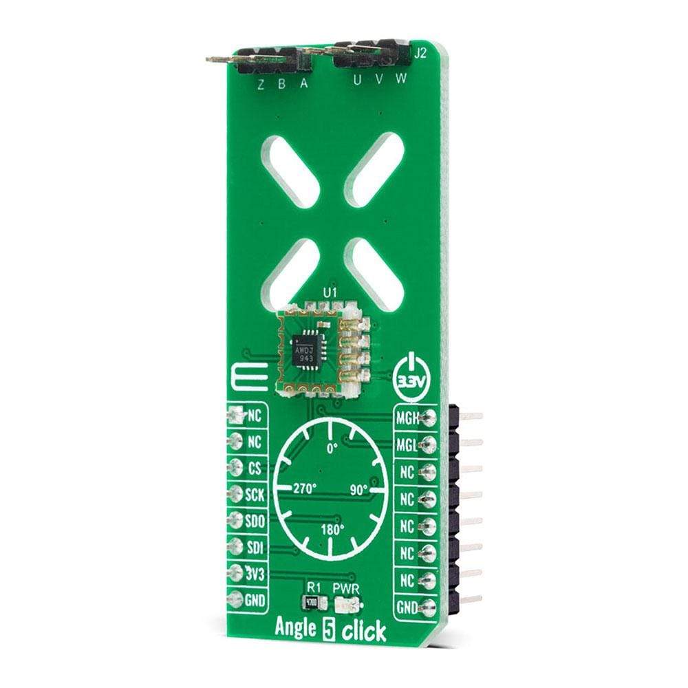
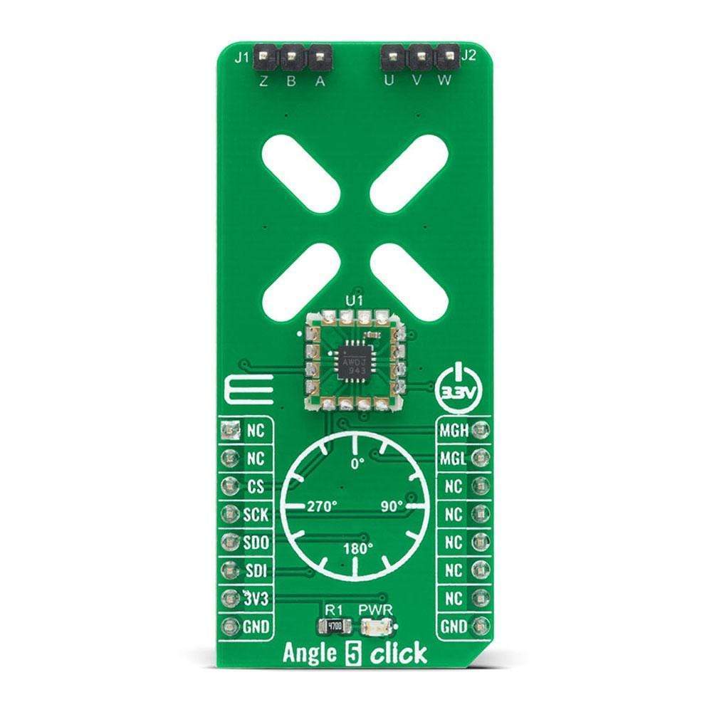
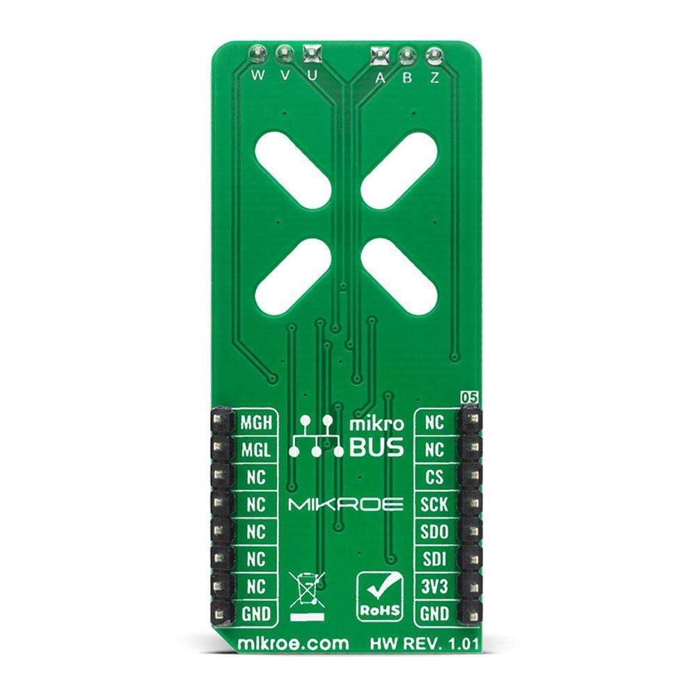
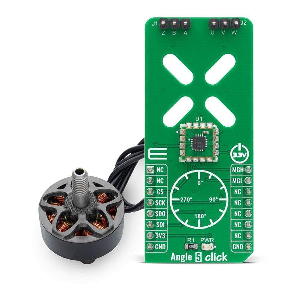
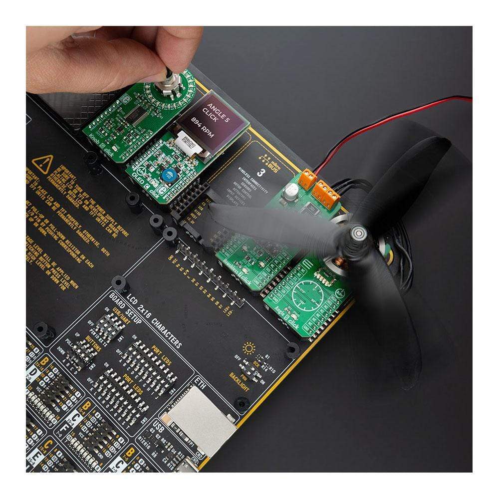
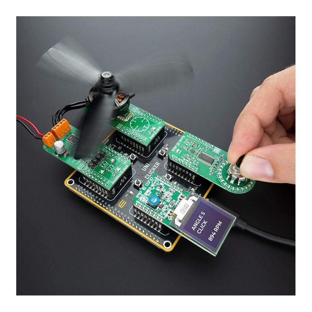
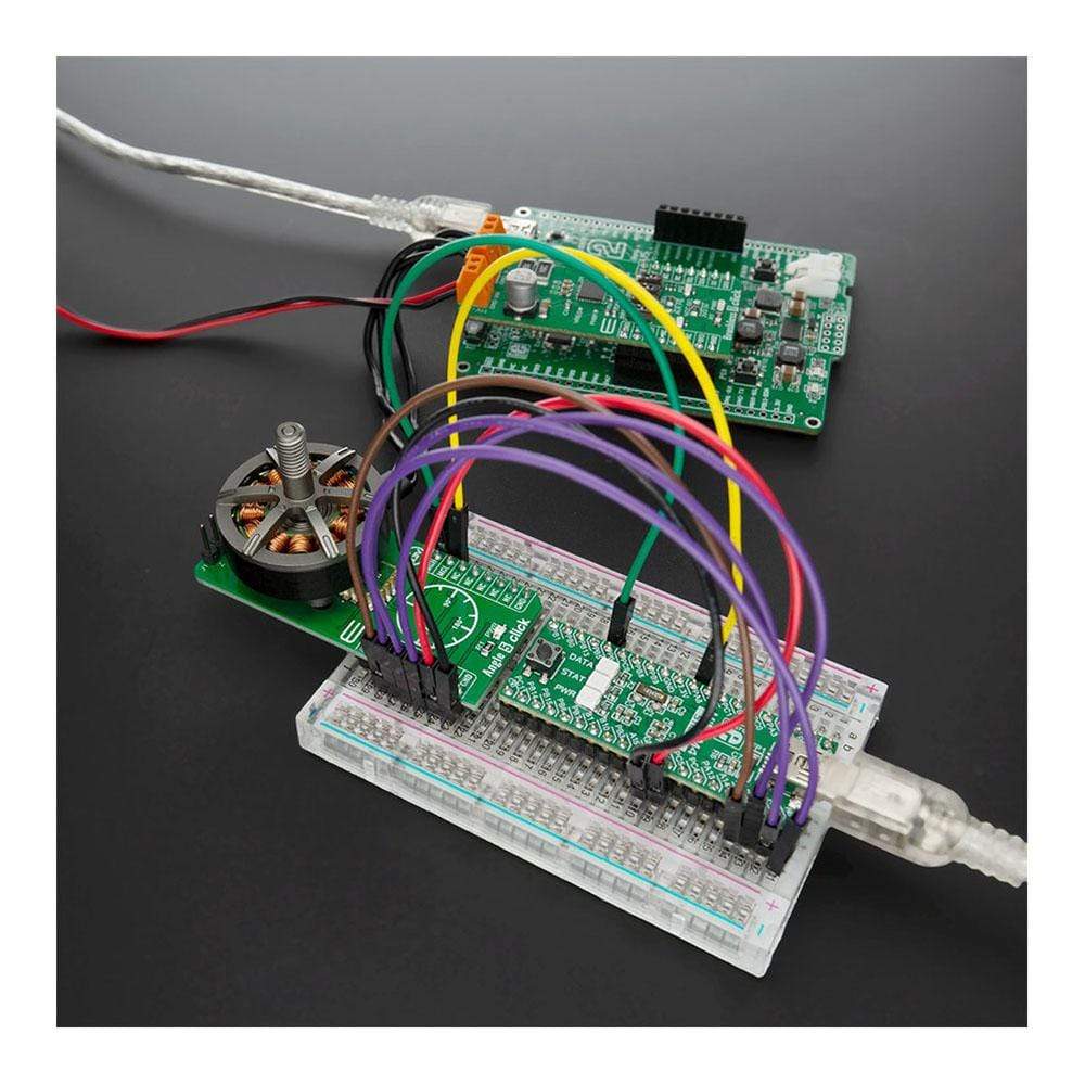
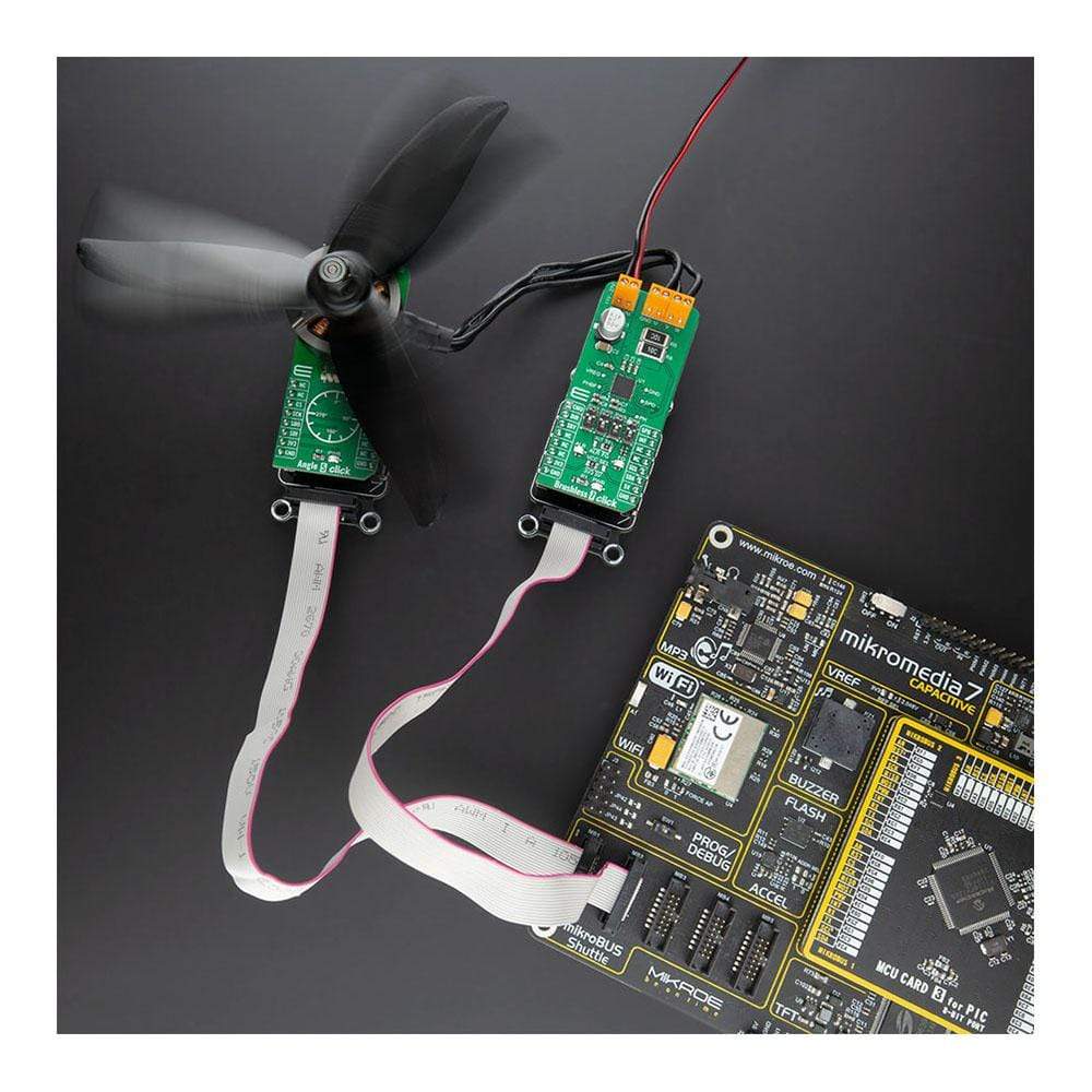
The Angle 5 Click Board™ is a compact add-on board that detects the absolute angular position of a permanent magnet, typically a diametrically magnetized cylinder on a rotating shaft. This board features the MA302, a 12-bit digital contactless angle sensor with ABZ and UVW incremental outputs from Monolithic Power Systems. The MA302 features an ABZ encoder, UVW pole pair emulation, fast data acquisition, and processing which provides accurate angle measurement at speeds from 0 to 60,000 rpm, and a magnetic field strength detection with programmable thresholds. This Click Board™ is suitable for various applications such as detecting the absolute rotor position of a brushless motor in real-time, even without a target magnet, by measuring the fringe field of the rotor.
Note: DC Motor doesn't come with this Click Board™, if you are interested you can find 2207V-2500KV BLDC Motor in our shop.
The Angle 5 Click Board™ is supported by a mikroSDK compliant library, which includes functions that simplify software development. This Click Board™ comes as a fully tested product, ready to be used on a system equipped with the mikroBUS™ socket.
Downloads
La carte Click Board™ Angle 5 est une carte complémentaire compacte qui détecte la position angulaire absolue d'un aimant permanent, généralement un cylindre diamétralement magnétisé sur un arbre rotatif. Cette carte comprend le MA302, un capteur d'angle sans contact numérique 12 bits avec sorties incrémentales ABZ et UVW de Monolithic Power Systems. Le MA302 est doté d'un encodeur ABZ, d'une émulation de paires de pôles UVW, d'une acquisition et d'un traitement rapides des données qui fournissent une mesure d'angle précise à des vitesses de 0 à 60 000 tr/min, et d'une détection de l'intensité du champ magnétique avec des seuils programmables. Cette carte Click Board™ convient à diverses applications telles que la détection de la position absolue du rotor d'un moteur sans balais en temps réel, même sans aimant cible, en mesurant le champ de franges du rotor.
Remarque : le moteur à courant continu n'est pas fourni avec cette Click Board™. Si vous êtes intéressé, vous pouvez trouver le moteur BLDC 2207V-2500KV dans notre boutique.
La carte Click Board™ Angle 5 est prise en charge par une bibliothèque compatible mikroSDK, qui comprend des fonctions qui simplifient le développement logiciel. Cette carte Click Board™ est un produit entièrement testé, prêt à être utilisé sur un système équipé du socket mikroBUS™.
| General Information | |
|---|---|
Part Number (SKU) |
MIKROE-4270
|
Manufacturer |
|
| Physical and Mechanical | |
Weight |
0.02 kg
|
| Other | |
EAN |
8606027380259
|
Frequently Asked Questions
Have a Question?
Be the first to ask a question about this.