


Mikroelektronika d.o.o.
Carte à clic AN vers PWM 2
Carte à clic AN vers PWM 2
SKU: MIKROE-4221
Impossible de charger la disponibilité du service de retrait


Overview
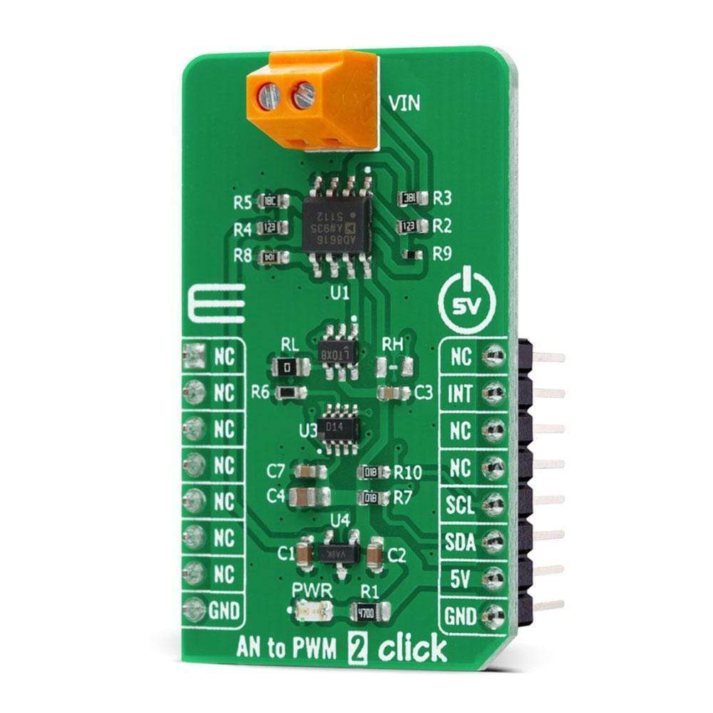
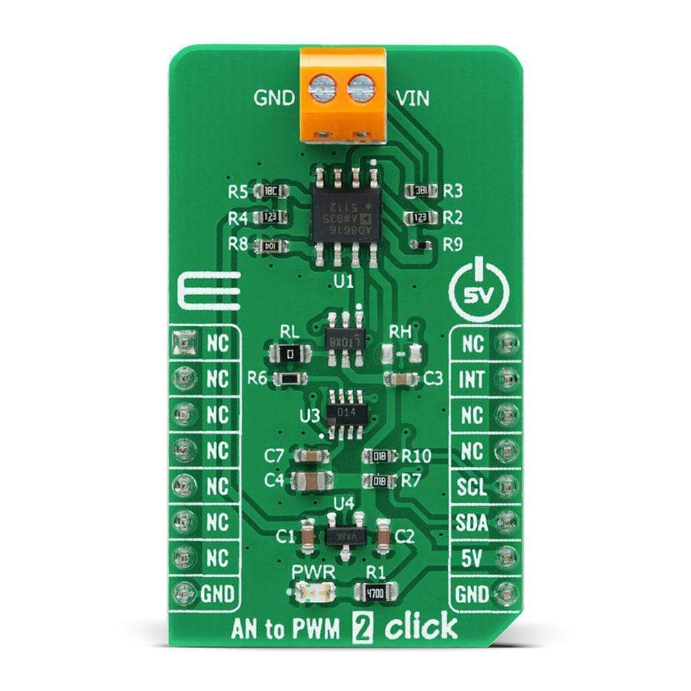
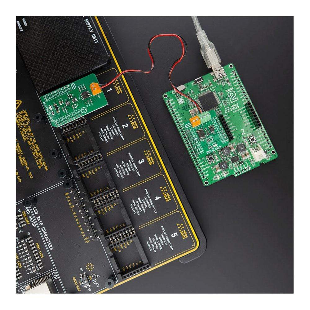
The AN to PWM 2 Click Board™ is a compact add-on board that contains an easy-to-use component that converts the value of the input analogue signal to a fixed frequency PWM voltage output, with a duty cycle proportional to the input voltage. This board features the LTC6992CS6, a silicon oscillator with an easy-to-use analogue voltage-controlled pulse width modulation (PWM) capability from Analog Devices. It features the PWM signal controlled by analogue input in the range of -2.5V to 2.5V, frequency range up to 1 MHz, frequency error less than 1.7%, and it has good temperature stability. It has many features that make it well suited for heater control, PWM servo loops, LED dimming, signal isolation, and other duty cycle control applications.
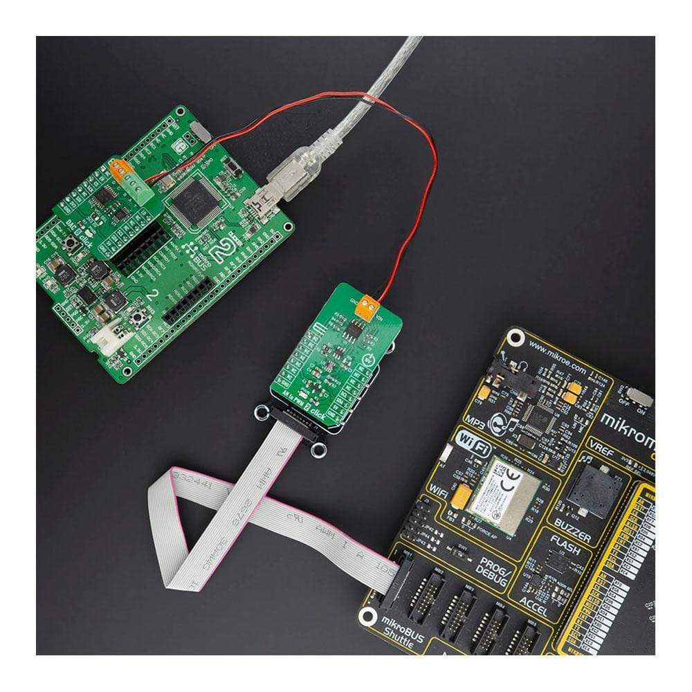
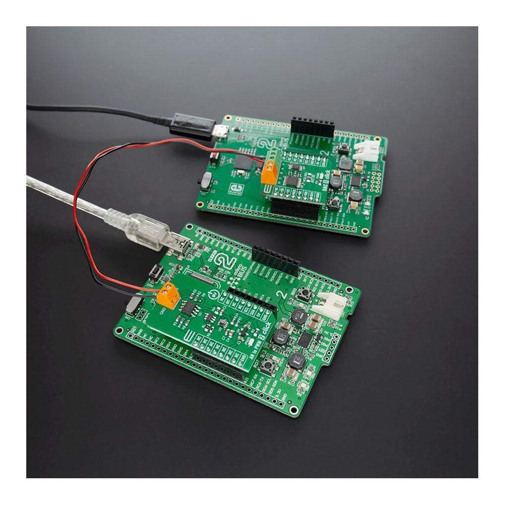
The AN to PWM 2 Click Board™ is supported by a mikroSDK compliant library, which includes functions that simplify software development. This Click Board™ comes as a fully tested product, ready to be used on a system equipped with the mikroBUS™ socket.
Downloads
Le Carte Click Board™ AN vers PWM 2 est une carte complémentaire compacte qui contient un composant facile à utiliser qui convertit la valeur du signal analogique d'entrée en une sortie de tension PWM à fréquence fixe, avec un cycle de service proportionnel à la tension d'entrée. Cette carte comprend le LTC6992CS6, un oscillateur au silicium avec une capacité de modulation de largeur d'impulsion (PWM) contrôlée par tension analogique facile à utiliser d'Analog Devices. Il dispose du signal PWM contrôlé par une entrée analogique dans la plage de -2,5 V à 2,5 V, une plage de fréquence jusqu'à 1 MHz, une erreur de fréquence inférieure à 1,7 % et une bonne stabilité de température. Il possède de nombreuses fonctionnalités qui le rendent bien adapté au contrôle du chauffage, aux boucles d'asservissement PWM, à la gradation des LED, à l'isolation du signal et à d'autres applications de contrôle du cycle de service.
La carte Click Board™ AN to PWM 2 est prise en charge par une bibliothèque compatible mikroSDK, qui comprend des fonctions qui simplifient le développement logiciel. Cette carte Click Board™ est un produit entièrement testé, prêt à être utilisé sur un système équipé du socket mikroBUS™.
| General Information | |
|---|---|
Part Number (SKU) |
MIKROE-4221
|
Manufacturer |
|
| Physical and Mechanical | |
Weight |
0.019 kg
|
| Other | |
EAN |
8606027380327
|
Frequently Asked Questions
Have a Question?
Be the first to ask a question about this.