Carte à clic H-Bridge 7
Overview
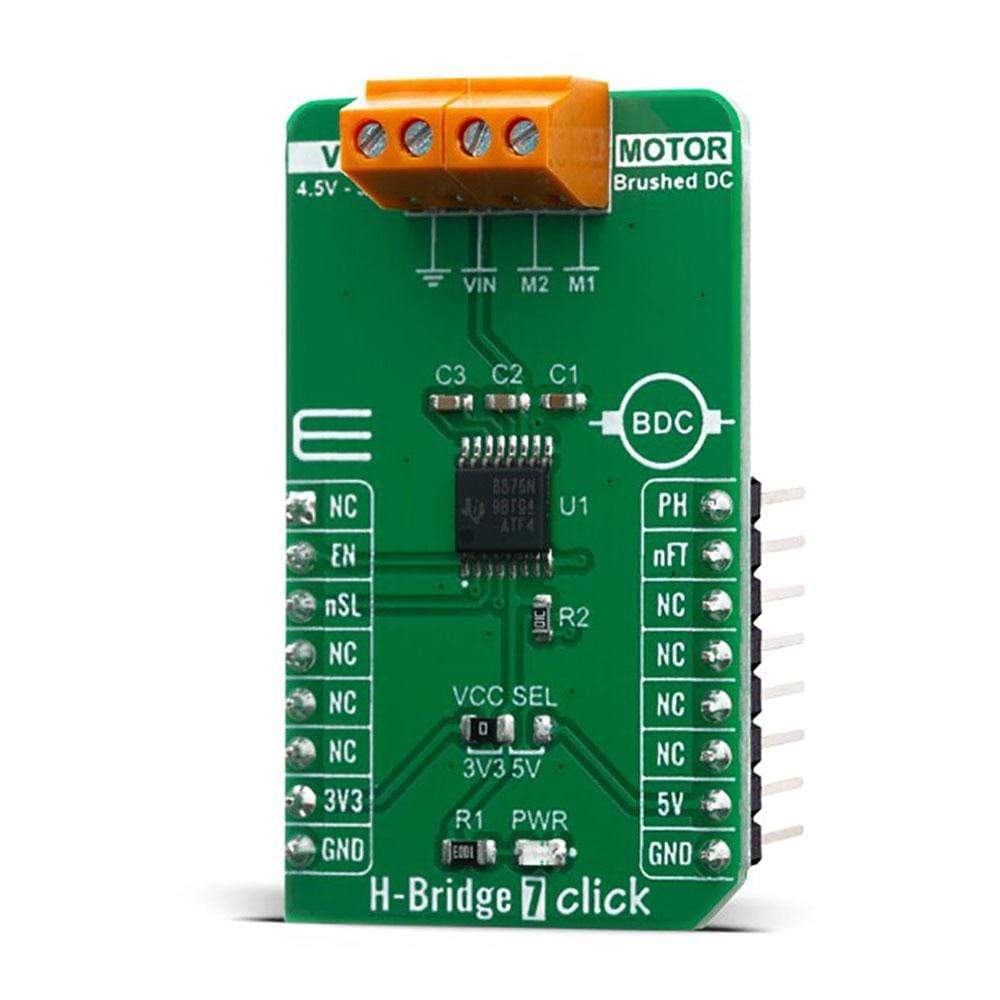
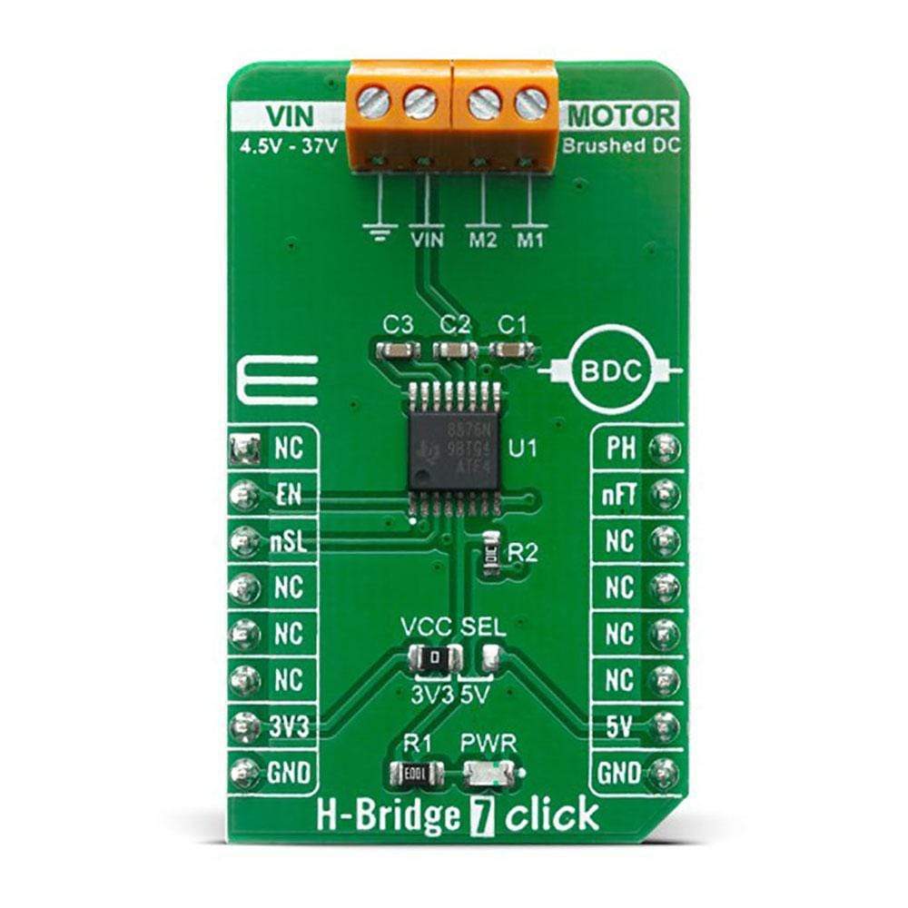
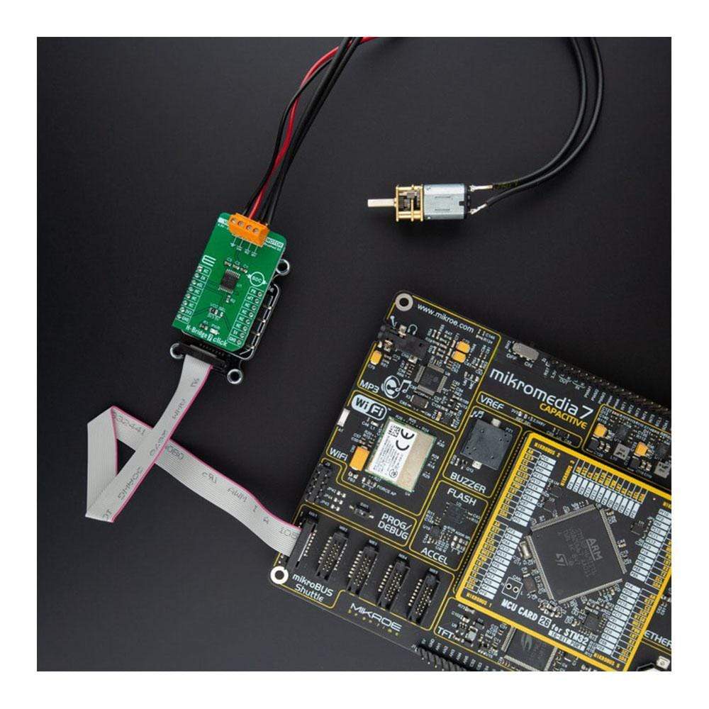
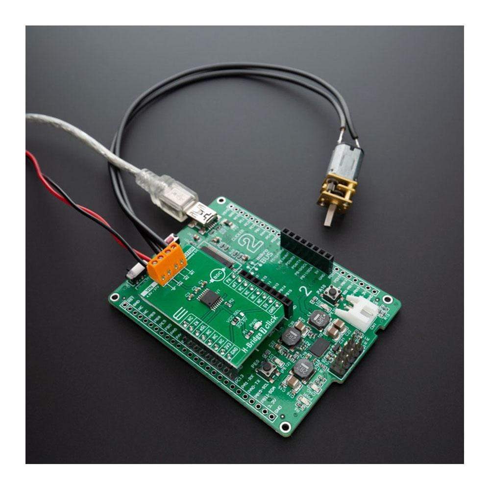
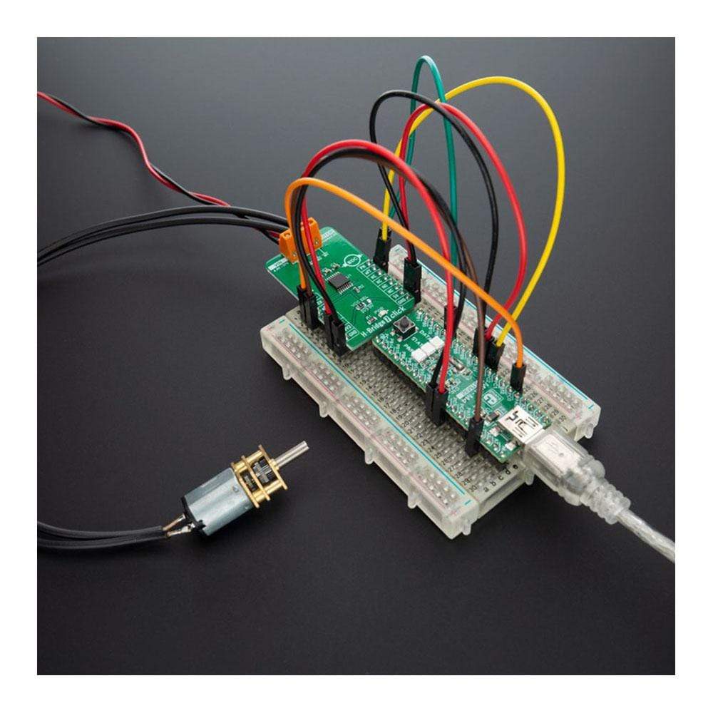
Le H-Bridge 7 Click Board™ est doté d'un circuit intégré de commande de moteur flexible pour une grande variété d'applications, étiqueté DRV8876N. Ce Click Board™ intègre un pont en H à canal N, un régulateur de pompe de charge et un circuit de protection. La pompe de charge améliore l'efficacité en permettant des MOSFET à canal N côté haut et côté bas et une prise en charge du cycle de service à 100 %.
Ce circuit intégré permet au H-Bridge 7 Click Board™ d'atteindre une consommation de courant de repos ultra-faible en arrêtant la plupart des circuits internes avec son mode veille à faible consommation. Des fonctions de protection internes sont fournies pour le verrouillage de sous-tension d'alimentation (UVLO), la sous-tension de la pompe de charge (CPUV), la surintensité de sortie (OCP) et la surchauffe de l'appareil (TSD). Les conditions de défaut sont indiquées sur la broche nFAULT (broche nFT sur mikroBUS™). Le H-Bridge 7 Click Board™ peut être utilisé pour les entraînements de moteurs à balais CC, les servomoteurs, les actionneurs, etc.
How Does The H-Bridge 7 Click Board™ Work?
The H-Bridge 7 Click Board™ uses the DRV8876N IC, N-channel H-bridge motor driver from Texas Instruments, that operates from a supply voltage of 4.5V to 37V supporting a wide range of output load currents for various types of motors and loads. This device integrates an H-bridge output power stage that can be operated in control modes that is set by the PMODE pin setting. The device also integrates a charge pump regulator to support more efficient high-side N-channel MOSFETs and 100% duty cycle operation. The device operates from a single power supply input (VM) which can be directly connected to a battery or DC voltage supply. The nSLEEP pin (nSL pin on the mikroBUS™) provides an ultra-low power mode to minimize current draw during system inactivity. Also, this device is fully protected against supply undervoltage, charge pump undervoltage, output overcurrent, and device overtemperature events.
The H-Bridge 7 Click Board™ support different control schemes with the EN/IN1 and PH/IN2 pins. The control mode is selected through the PMODE pin with either logic low, logic high, or setting the pin Hi-Z (in this case PMODE is on the logic low level which means that the device is latched into PH/EN mode). PH/EN mode allows for the H-bridge to be controlled with a speed and direction type of interface.
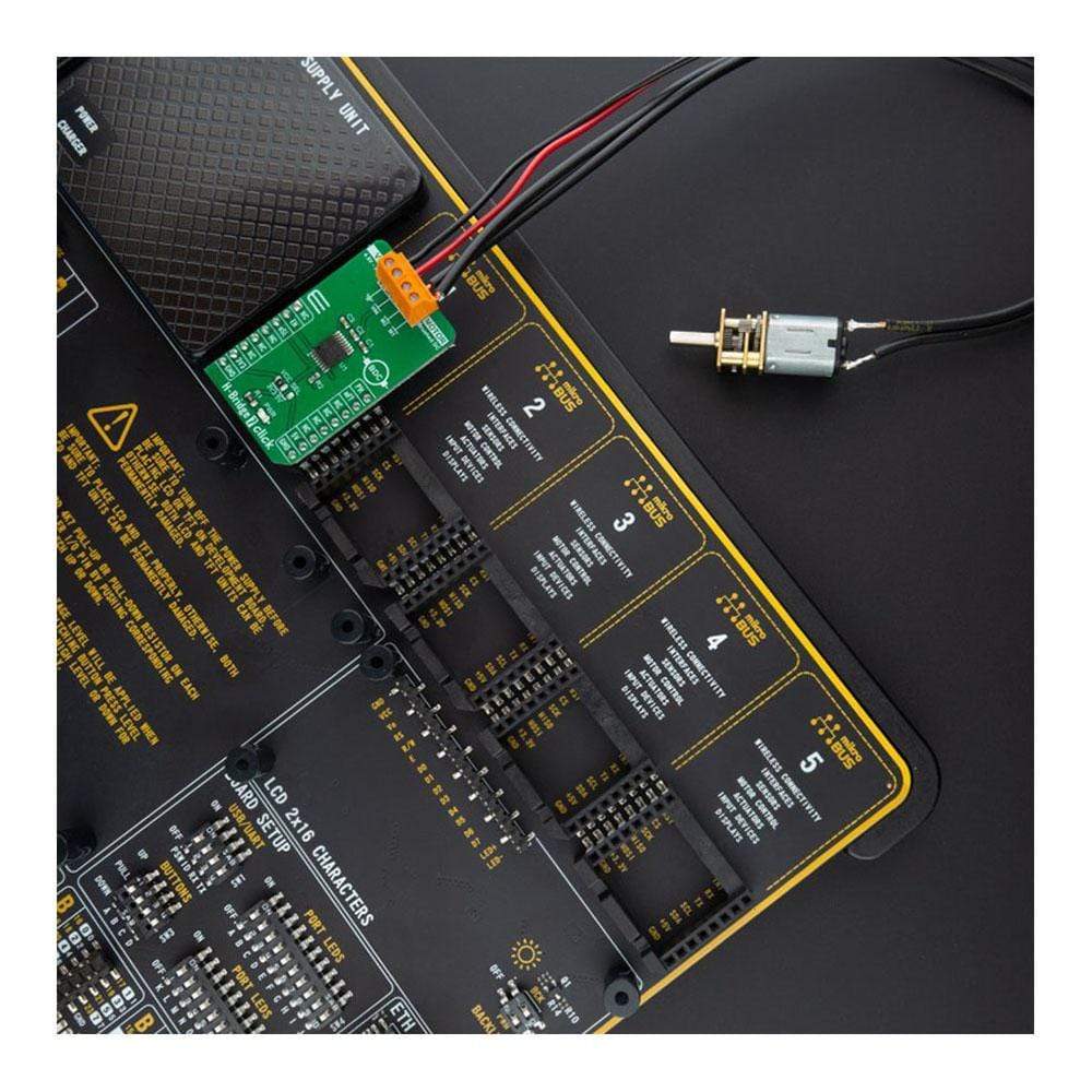
In this configuration, Click board™ drives a bidirectional current through an external load (such as a brushed DC motor), and the H-bridge polarity and duty cycle are controlled with a PWM and IO resource from the external controller to the EN/IN1 and PH/IN2 pins. The device is then configured for the PH/EN control mode by tying the PMODE pin to GND. Some applications of DRV8876N includes brushed DC motors, solenoids, and actuators, but also can be utilized to drive many common passive loads such as LEDs, resistive elements, relays, etc.
An onboard SMD jumper, labelled as VCC SEL is used to set the voltage levels for the EN/IN1, PH/IN2, nFAULT, and nSLEEP pins of the DRV8876N. It allows for both 3.3V and 5V MCUs to be interfaced with the H-Bridge 7 Click Board™. More information about the DRV8876N can be found in the attached datasheet. However, this Click board™ comes equipped with a library that contains easy to use functions and a usage example that may be used as a reference for the development.
Specifications
Type | Brushed |
Applications | Can be used for DC Brush motor drive, servo motors, actuators, and more. |
On-board modules | H-Bridge 7 Click uses the DRV8876N IC, N-channel H-bridge motor driver from Texas Instruments, that operates from a supply voltage of 4.5V to 37V supporting a wide range of output load currents for various types of motors and loads. |
Key Features | N-channel H-bridge, charge pump regulator, protection circuitry, Undervoltage lockout, charge pump Undervoltage, output overcurrent, device overtemperature protection |
Interface | GPIO |
Compatibility | mikroBUS |
Click board size | M (42.9 x 25.4 mm) |
Input Voltage | 3.3V or 5V |
Pinout diagram
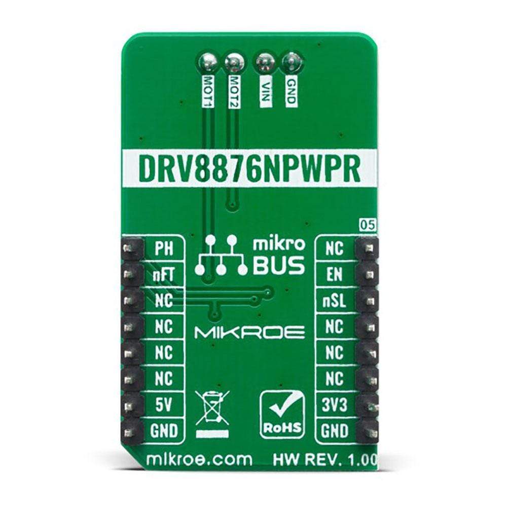
This table shows how the pinout on H-Bridge 7 Click corresponds to the pinout on the mikroBUS™ socket (the latter shown in the two middle columns).
Notes | Pin | Pin | Notes | ||||
---|---|---|---|---|---|---|---|
NC | 1 | AN | PWM | 16 | PH | H-bridge control 2 | |
H-bridge control 1 | EN | 2 | RST | INT | 15 | nFT | Fault indicator |
Sleep mode | nSL | 3 | CS | RX | 14 | NC | |
NC | 4 | SCK | TX | 13 | NC | ||
NC | 5 | MISO | SCL | 12 | NC | ||
NC | 6 | MOSI | SDA | 11 | NC | ||
Power Supply | 3.3V | 7 | 3.3V | 5V | 10 | 5V | Power Supply |
Ground | GND | 8 | GND | GND | 9 | GND | Ground |
Onboard settings and indicators
Label | Name | Default | Description |
---|---|---|---|
LD1 | PWR | - | Power LED Indicator |
JP1 | VCC SEL | Left | Logic Voltage Level Selection 3V3/5: Left position 3V3, Right position 5V |
TB1 | POWER | - | 4.5V to 37V Power Supply Input |
TB2 | MOTOR | - | H-bridge Output |
Maximum Ratings (Limiting Conditions)
Description | Min | Typ | Max | Unit |
---|---|---|---|---|
Supply Voltage (VM) | -0.3 | - | +40 | V |
Logic Pin Voltage (GPIO) | -0.3 | - | 5.75 | V |
Maximum Output Current | 0 | - | 3.5 | A |
Operating Temperature Range | -40 | - | +125 | °C |
We provide a library for the H-Bridge 7 Click Board™ on our LibStock page, as well as a demo application (example), developed using MikroElektronika compilers. The demo can run on all the main MikroElektronika development boards.
Library Description
The library contains basic functions for working with the H-Bridge 7 click.
Key Functions
void hbridge7_motor_state ( uint8_t state )
- Set motor statevoid hbridge7_motor_control ( uint8_t ctrl )
- Set motor controluint8_t hbridge7_get_fault_state ( void )
- Get Fault pin state
Example Description
The application is composed of three sections :
- System Initialization - Initializes all necessary GPIO pins for motor control.
- Application Initialization - Initializes driver init and activates the motor.
- Application Task - Changes the direction of the motor.
void application_task ( ) { hbridge7_motor_control( HBRIDGE7_MOTOR_FORWARD ); Delay_ms( 3000 ); hbridge7_motor_control( HBRIDGE7_MOTOR_BACKWARD ); Delay_ms( 3000 ); hbridge7_motor_control( HBRIDGE7_MOTOR_STOP ); Delay_ms( 3000 ); }
GPIO
The full application code, and ready to use projects can be found on our LibStock page.
Other mikroE Libraries used in the example:
- GPIO
Additional Notes and Information
Depending on the development board you are using, you may need a USB UART click, USB UART 2 click or RS232 click to connect to your PC, for development systems with no UART to USB interface available on the board. The terminal available in all MikroElektronika compilers, or any other terminal application of your choice, can be used to read the message.
mikroSDK
The H-Bridge 7 Click Board™ is supported with mikroSDK - MikroElektronika Software Development Kit. To ensure proper operation of mikroSDK compliant Click board™ demo applications, mikroSDK should be downloaded from the LibStock and installed for the compiler you are using.
Frequently Asked Questions
Have a Question?
Be the first to ask a question about this.
Frequently Asked Questions
Have a Question?
Be the first to ask a question about this.
Frequently Asked Questions
Have a Question?
Be the first to ask a question about this.
Frequently Asked Questions
Have a Question?
Be the first to ask a question about this.