Carte Click esclave M-Bus
Overview
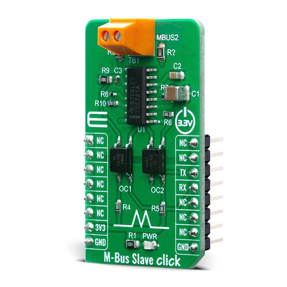
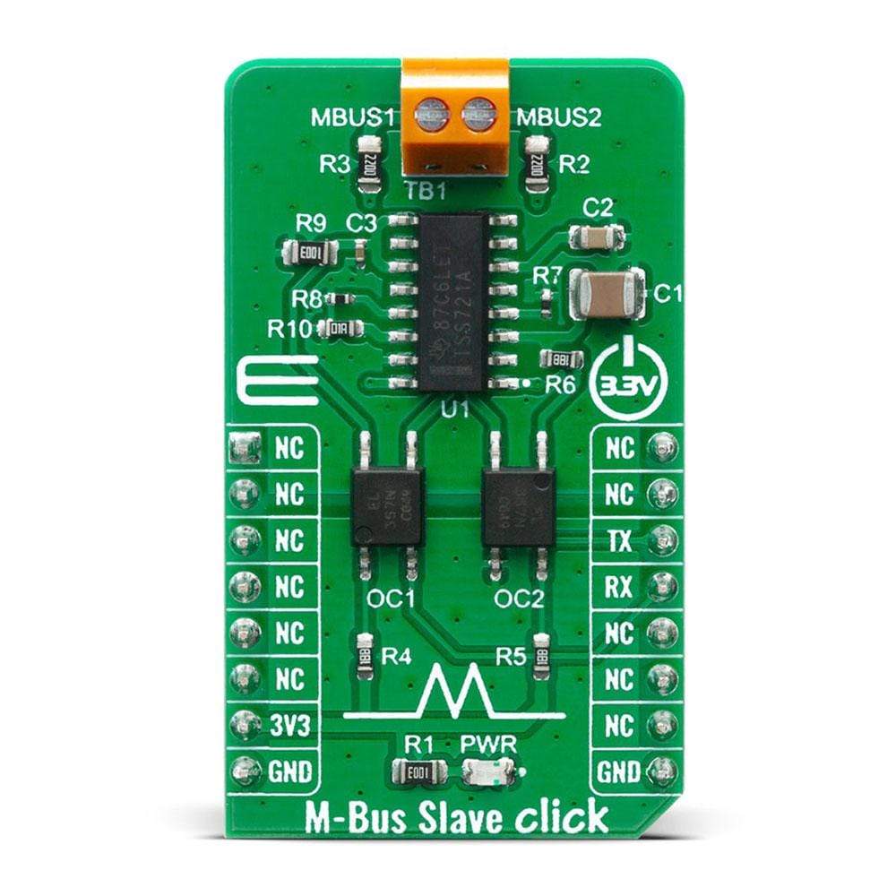
La carte Click Board M-Bus Slave™ est équipé du TSS721A, un émetteur-récepteur monopuce développé par Texas Instruments pour les applications Meter-Bus selon la norme EN1434-3. La connexion au bus est indépendante de la polarité et sert de nœud esclave dans le système.
Le M-Bus Slave Click Board™ est doté d'une isolation galvanique complète avec optocoupleurs pour améliorer la fiabilité de l'ensemble du circuit. Le circuit est alimenté par le maître via le bus. Par conséquent, ce circuit n'offre aucune charge supplémentaire pour la batterie esclave. Le TSS721A dispose d'une fonction de coupure de courant intégrée. Cette solution est parfaite pour une multitude d'applications telles que la lecture à distance de compteurs de gaz, d'eau, de chaleur ou d'électricité, ou d'autres types de compteurs de consommation.
How Does The M-Bus Click Board™ Work?
M-Bus is a bus system used for the remote reading of gas, water, heat, electricity, etc. It also supports various sensors and actuators. This is a cost-optimized bus for the transfer of energy consumption data since it is made for communication on only two wires. M-Bus can be used in the industry, but also, it's convenient to be used in private households. By the standard, M-Bus master can read up to 250 slave devices. They can be meters, water, electrical, or gas meters. You can also use M-bus in applications like alarm systems, flexible illumination installations, heating control, etc. It can monitor different consumption meters, and it can monitor any leakage.
One of the biggest advantages of M-Bus are:
- All data reading is accomplished remotely.
- It is a very simple protocol – it uses only two wires, and it uses a power supply from the users which are connected to the wire.
- Reading errors are minimal. Also, reading is very fast. Further processing is very easy since the received data is presented in a machine-readable form.
- There are no special cables – you can use a telephone cable. With that one cable, you can attach all the meters in the housing with all the meters individually addressable. This way you can have control over each consumption meter while using only one connection cable.
The M-Bus Slave Click Board™ uses the TSS721A, a single chip transceiver developed for Meter-Bus standard (EN1434-3) applications. The connection to the bus is polarity independent and serves as a slave node in the system. The M-Bus Slave Click Board™ has full galvanic isolation with optocouplers to improve the reliability of the whole circuit. The circuit is supplied by the master via the bus. The benefit of the TSS721A in M-Bus slaves is the reduction of the number of components needed, and therefore the cost of slaves. Apart from the transmission and reception of data by the M-Bus specification, this IC also provides translation from and to the operating voltage of the microprocessor to which it is connected, to be able to communicate with it. The communication can take place at baud rates from 300 to 9600 Baud. Additional features include integrated protection against reversed polarity, a constant 3.3V power supply for the microprocessor, and the prompt indication of failure of the bus voltage.
SPECIFICATIONS
Type | RS232 |
Applications | Remote sensor reading, remote control over M-Bus |
On-board modules | The M-Bus Slave Click Board™ uses the TSS721A IC, a single chip transceiver developed for Meter-Bus standard, from Texas Instruments |
Key Features | Galvanically isolated, Slave node |
Interface | UART |
Compatibility | mikroBUS |
Click board size | M (42.9 x 25.4 mm) |
Input Voltage | 3.3V |
PINOUT DIAGRAM
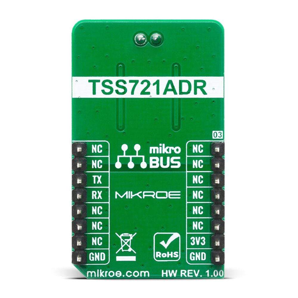
This table shows how the pinout on the M-Bus Slave Click Board™ corresponds to the pinout on the mikroBUS™ socket (the latter shown in the two middle columns).
Notes | Pin | Pin | Notes | ||||
---|---|---|---|---|---|---|---|
NC | 1 | AN | PWM | 16 | NC | ||
NC | 2 | RST | INT | 15 | NC | ||
NC | 3 | CS | RX | 14 | TX | UART TX | |
NC | 4 | SCK | TX | 13 | RX | UART RX | |
NC | 5 | MISO | SCL | 12 | NC | ||
NC | 6 | MOSI | SDA | 11 | NC | ||
Power Supply | 3.3V | 7 | 3.3V | 5V | 10 | NC | |
Ground | GND | 8 | GND | GND | 9 | GND | Ground |
ONBOARD SETTINGS AND INDICATORS
Label | Name | Default | Description |
---|---|---|---|
LD1 | PWR | - | Power LED Indicator |
M-BUS SLAVE CLICK ELECTRICAL SPECIFICATIONS
Description | Min | Typ | Max | Unit |
---|---|---|---|---|
Supply Voltage | -0.3 | 3.3 | 3.5 | V |
M-Bus Voltage Level | -50 | - | 50 | V |
Operating Temperature Range | -55 | - | 85 | °C |
Software Support
We provide a library for the M-Bus Slave Click Board™ on our LibStock page, as well as a demo application (example), developed using MikroElektronika compilers. The demo can run on all the main MikroElektronika development boards.
Library Description
The library covers all the necessary functions to control the M-Bus Slave Click Board™. The library performs a standard UART interface communication.
Key Functions
void mbus_write_byte ( uint8_t input )
- Write Single Byte.uint8_t mbus_read_byte( void )
- Read Single Byte.uint8_t mbus_byte_ready ( void )
- Check for new byte received.
Example Description
The application is composed of three sections :
- System Initialization - Initializes peripherals.
- Application Initialization - Initializes UART serial interface and app mode.
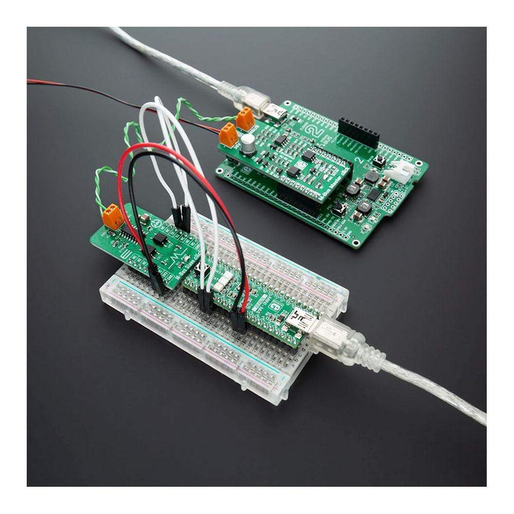
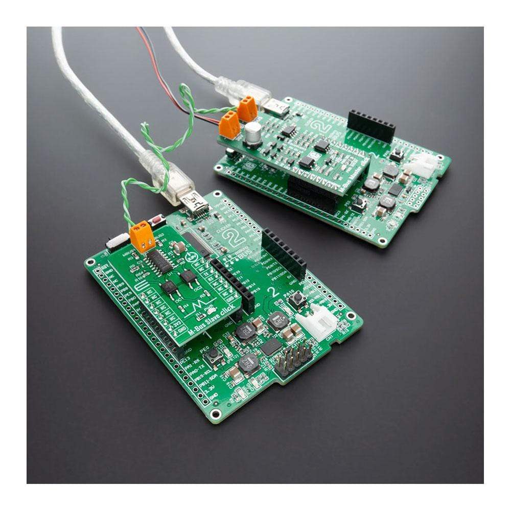
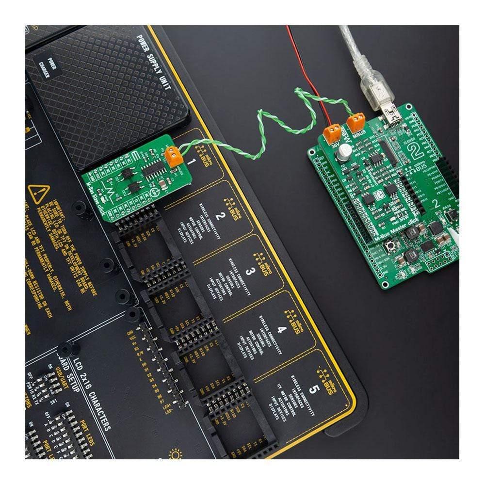
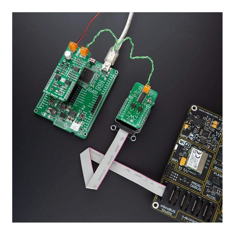
- Application Task - (code snippet) This is an example that demonstrates the use of the M-BUS Click board. In this example, depending on the app mode selected, we send ( receive ) a message to ( from ) the M-BUS Master Click which is connected via cable to M-BUS Click ( slave ). Results are being sent to the Usart Terminal where you can track their changes. All data logs written on USB uart changes approximately every 2 sec.
void application_task ( ) { char tmp; uint8_t drdy_flag; if ( app_mode == APP_MODE_RECEIVER ) { // RECEIVER - UART polling drdy_flag = mbus_byte_ready( ); if ( 1 == drdy_flag ) { tmp = mbus_read_byte( ); mikrobus_logWrite( &tmp, _LOG_BYTE ); } } else { // TRANSMITER - TX each 2 sec for ( tmp = 0; tmp < 9; tmp++ ) { mbus_write_byte( demo_message_data[ tmp ] ); mikrobus_logWrite( " >> MESSAGE SENT <<", _LOG_LINE ); Delay_ms( 100 ); } Delay_ms( 2000 ); } }
The full application code, and ready to use projects can be found on our LibStock page.
Other mikroE Libraries used in the example:
- UART
Additional Notes and Information
Depending on the development board you are using, you may need a USB UART click, USB UART 2 click or RS232 click to connect to your PC, for development systems with no UART to USB interface available on the board. The terminal available in all MikroElektronika compilers, or any other terminal application of your choice, can be used to read the message.
MIKROSDK
The M-Bus Slave Click Board™ is supported with mikroSDK - MikroElektronika Software Development Kit. To ensure proper operation of mikroSDK compliant Click board™ demo applications, mikroSDK should be downloaded from the LibStock and installed for the compiler you are using.
Frequently Asked Questions
Have a Question?
Be the first to ask a question about this.