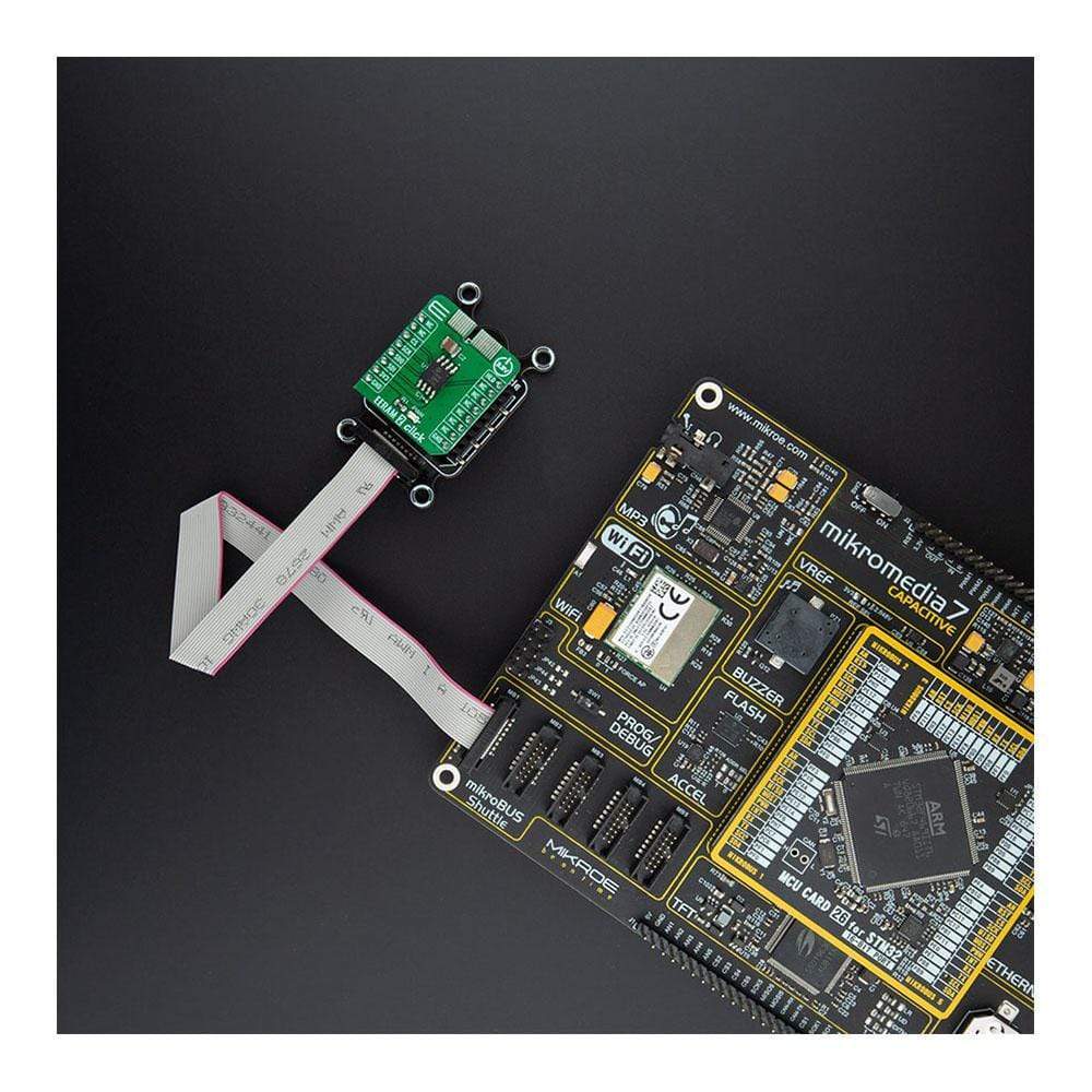
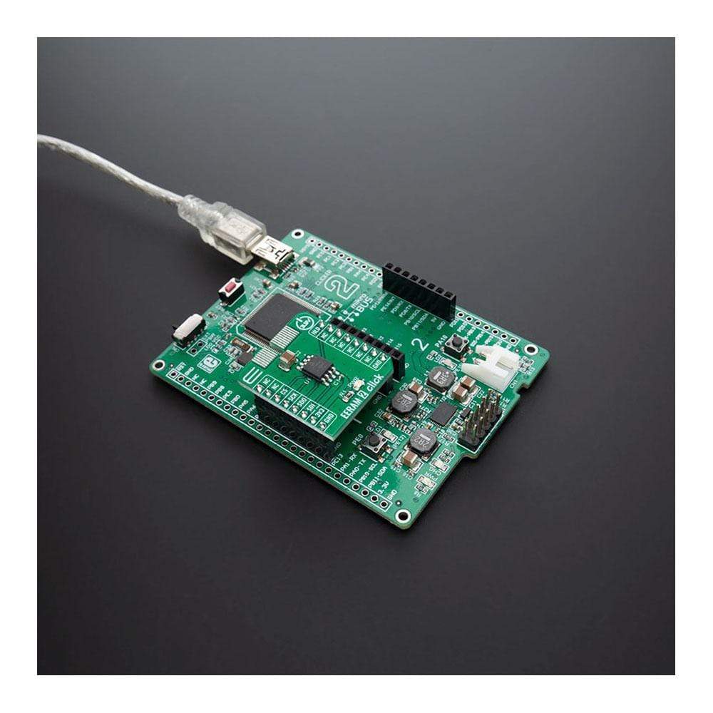
Carte à clic EERAM 2
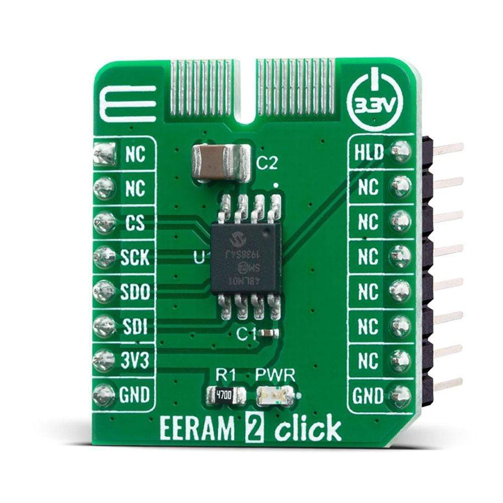
La carte EERAM 2 Click Board™ est une mémoire SRAM série autonome qui inclut une sauvegarde non volatile fantôme. L'EERAM utilise un petit condensateur externe pour fournir l'énergie nécessaire pour déplacer le contenu de la SRAM vers les cellules non volatiles lorsque l'alimentation du système est coupée. Contrairement à la NVSRAM, aucune batterie externe n'est nécessaire. L'EERAM offre des cycles de lecture et d'écriture SRAM illimités et plus de 100 000 sauvegardes sur les cellules non volatiles.
Les pannes de courant étant généralement aléatoires ou imprévisibles, la mémoire EERAM fonctionne dans des applications qui ne peuvent absolument pas perdre les données SRAM qui changent rapidement en cas de panne de courant soudaine. Elle fournit aux concepteurs d'une boîte noire/d'un enregistrement de données ou de systèmes de surveillance un moyen sûr et précis de stocker de manière sûre, fiable et automatique les derniers octets de données avant la panne de courant. Le Vcc est surveillé à l'intérieur du circuit intégré et peut gérer automatiquement le mouvement des données entre la mémoire SRAM et la mémoire non volatile en cas de panne de courant.
How Does The EERAM 2 Click Board™ Work?
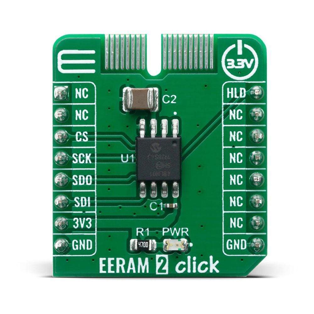
The EERAM 2 Click Board™ is a static RAM (SRAM) memory Click Board™ board™ with hidden EEPROM backup. This device can be treated by the user as a full symmetrical read/write SRAM with no limits on cell usage. Backup to EEPROM is handled by the device on any power disrupt, so the user can effectively view this device as an SRAM that never loses its data. The 48LM01 memory IC from Microchip, is structured as a 1024-Kbit SRAM with EEPROM backup in each memory cell. The SRAM is organized as 131,072 x 8 bits with access via the SPI serial interface. The backup EEPROM is invisible and cannot be accessed by the user independently. The 48LM01 includes circuitry that detects VCC dropping below a certain threshold, shuts its connection to the outside environment, and transfers all SRAM data to the EEPROM portion of each cell for safekeeping. When VCC returns, the circuitry automatically returns the data to the SRAM and the user's interaction with the SRAM can continue with the same data set.
When power is first applied to the Click Board™, the VCAP capacitor is charged to VCC through the 48LM01 IC. During normal SRAM operation, the capacitor remains charged and the level of system VCC is monitored by the device. If the system VCC drops below a set threshold, the device interprets this as a power-off or brown-out event. The device suspends all I/O operation, shuts off its connection with the VCC pin, and uses the saved energy in the capacitor to power the device through the VCAP pin as it transfers all SRAM data to EEPROM. On the next power-up of VCC, the data is transferred back to SRAM, the capacitor is recharged, and the SRAM operation continues.
Besides standard 4-wire SPI lines, 48LM01 has an additional HOLD pin. This pin can be used for transmission suspend to the 48LM01 while in the middle of a serial sequence without having to retransmit the entire sequence over again. It must be held high any time this function is not being used. Once the device is selected and a serial sequence is underway, the HOLD pin may be pulled low to pause further serial communication without resetting the serial sequence.
The 48LM01 is internally organized as a continuous SRAM array for both reading and writing, along with a non-volatile EEPROM array that is not directly accessible to the user, but which can be refreshed or recalled on power cycles or on software commands. The SRAM array is continuously addressable, so the entire array can be written without having to access pages.
The EERAM 2 Click Board™ uses the SPI communication interface and is designed to be operated only with a 3.3V logic level. A proper logic voltage level conversion should be performed before the Click board™ is used with MCUs with different logic levels.
SPECIFICATIONS
Type | EERAM |
Applications | Provides an additional RAM memory for a wide range of embedded applications, especially useful if retaining of the working parameters is required upon the power failure or power off cycle |
On-board modules | EERAM 2 Click uses the 48LM01 IC, a high accuracy temperature sensor, from Microchip |
Key Features | Unlimited reads/writes on 1 Mbit of SRAM, with the automatic backup and recall to/from the integrated EEPROM, upon power-down. High-speed SPI interface on up to 66 MHz. |
Interface | GPIO,SPI |
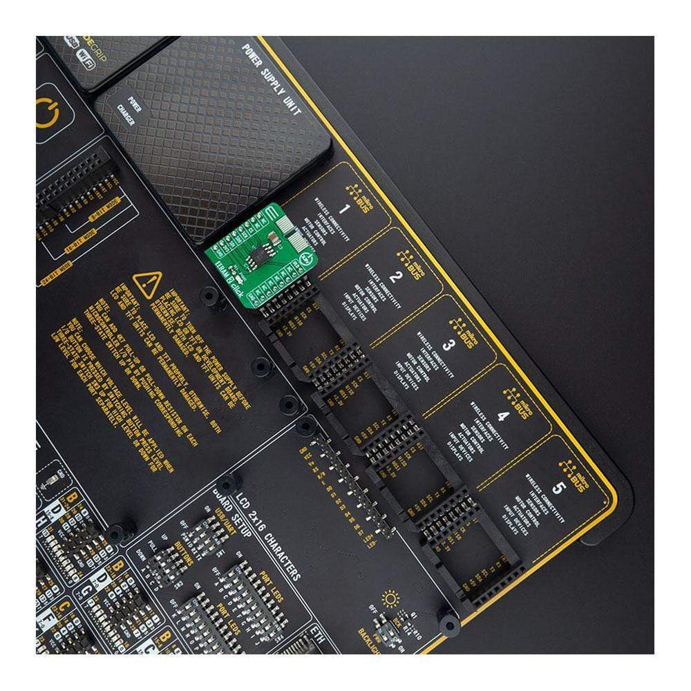
Compatibility | mikroBUS |
Click board size | S (28.6 x 25.4 mm) |
Input Voltage | 3.3V |
PINOUT DIAGRAM
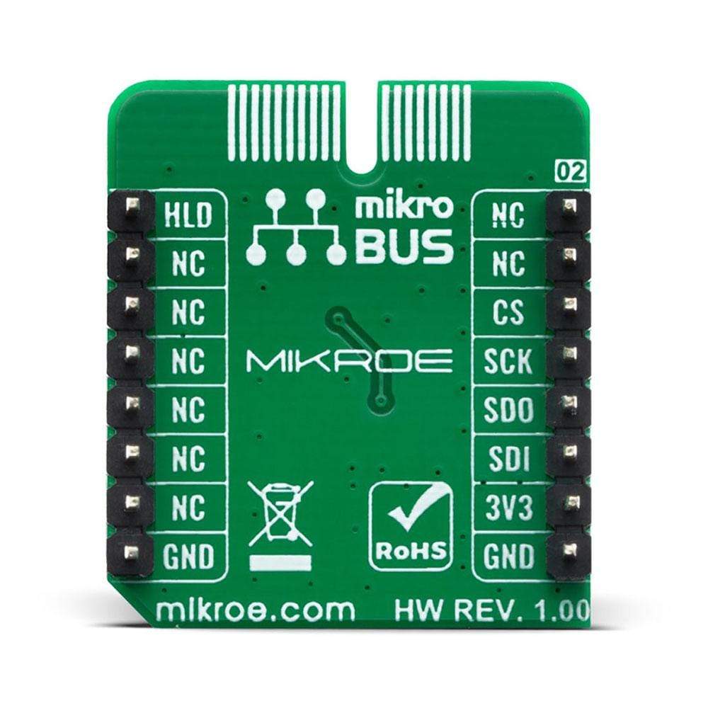
This table shows how the pinout of the EERAM 2 Click Board™ corresponds to the pinout on the mikroBUS™ socket (the latter shown in the two middle columns).
Notes | Pin | Pin | Notes | ||||
---|---|---|---|---|---|---|---|
NC | 1 | AN | PWM | 16 | HLD | Hold | |
NC | 2 | RST | INT | 15 | NC | ||
SPI Chip Select | CS | 3 | CS | RX | 14 | NC | |
SPI Clock | SCK | 4 | SCK | TX | 13 | NC | |
SPI Data OUT | SDO | 5 | MISO | SCL | 12 | NC | |
SPI Data IN | SDI | 6 | MOSI | SDA | 11 | NC | |
Power Supply | 3.3V | 7 | 3.3V | 5V | 10 | NC | |
Ground | GND | 8 | GND | GND | 9 | GND | Ground |
ONBOARD SETTINGS AND INDICATORS
Label | Name | Default | Description |
---|---|---|---|
LD1 | PWR | - | Power LED Indicator |
Software Support
We provide a library for the EERAM 2 Click Board™ on our LibStock page, as well as a demo application (example), developed using MikroElektronika compilers. The demo can run on all the main MikroElektronika development boards.
Library Description
The library covers all the necessary functions to control the EERAM 2 Click Board™. A library performs the communication with the 48LM01 1-Mbit SPI Serial EERAM on the EERAM 2 Click Board™ board.
Key Functions
void eeram2_set_write_status ( uint8_t en_write )
- Set write status function.EERAM2_RETVAL_T eeram2_write_continuous ( uint32_t reg, uint8_t *p_tx_data, uint8_t n_bytes )
- Continuous write the data into SRAM function.EERAM2_RETVAL_T eeram2_read_continuous ( uint32_t reg, uint8_t *p_rx_data, uint8_t n_bytes )
- Continuous read the data into SRAM function.
Example Description
The application is composed of three sections :
- System Initialization - Initializes SPI, sets CS nad PWM pin as outputs and begins to write log.
- Application Initialization - Initialization driver enables - SPI, disabled SPI communication pause with the device and set write enable instruction.
- Application Task - (code snippet) This is an example that demonstrates the use of the EERAM 2 Click board. In this example, we write and then read data from SRAM memory. Results are being sent to the USART Terminal where you can track their changes. All data logs write on USB UART changes approximately for every 1 sec.
void application_task ( ) { check_status = eeram2_write_continuous( 0x00543210, &demo_data[ 0 ], 9 ); if ( check_status == EERAM2_ERROR ) { mikrobus_logWrite( " ERROR Writing ", _LOG_LINE ); mikrobus_logWrite( "--------------------", _LOG_LINE ); for ( ; ; ); } mikrobus_logWrite( " Writing... ", _LOG_LINE ); mikrobus_logWrite( "--------------------", _LOG_LINE ); Delay_ms( 100 ); check_status = eeram2_read_continuous( 0x00543210, &read_data[ 0 ], 9 ); if ( check_status == EERAM2_ERROR ) { mikrobus_logWrite( " Reading ERROR ", _LOG_LINE ); mikrobus_logWrite( "--------------------", _LOG_LINE ); for ( ; ; ); } mikrobus_logWrite( " Read data : ", _LOG_TEXT ); for ( cnt = 0; cnt < 9; cnt++ ) { mikrobus_logWrite( &read_data[ cnt ], _LOG_BYTE ); } mikrobus_logWrite( "--------------------", _LOG_LINE ); Delay_ms( 1000 ); }
The full application code, and ready to use projects can be found on our LibStock page.
Other mikroE Libraries used in the example:
- SPI
- UART
- Conversions
Additional Notes and Information
Depending on the development board you are using, you may need USB UART Click Board™, USB UART 2 Click Board™ or RS232 Click Board™ to connect to your PC, for development systems with no UART to USB interface available on the board. The terminal available in all MikroElektronika compilers, or any other terminal application of your choice, can be used to read the message.
MIKROSDK
The EERAM 2 Click Board™ is supported with mikroSDK - MikroElektronika Software Development Kit. To ensure proper operation of mikroSDK compliant Click board™ demo applications, mikroSDK should be downloaded from the LibStock and installed for the compiler you are using.
Carte à clic EERAM 2
Frequently Asked Questions
Have a Question?
Be the first to ask a question about this.