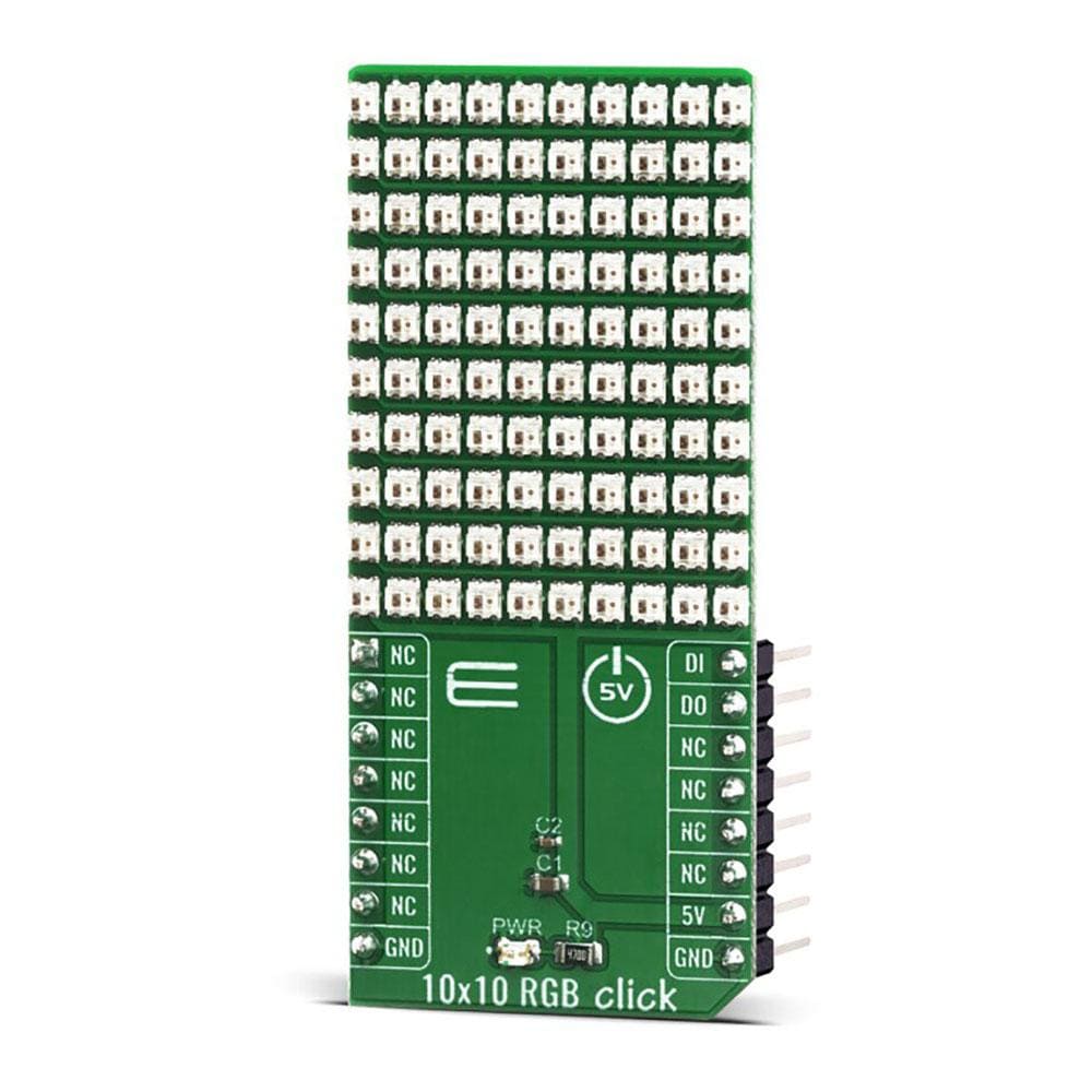
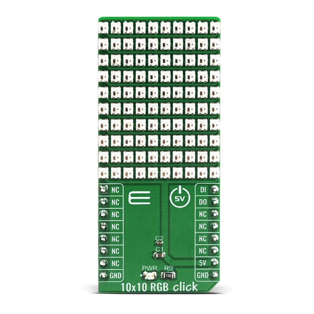
Carte à clic RVB 10x10
Améliorez vos projets avec le Click Board™ RGB 10x10 polyvalent et innovant. Cette matrice de 100 éléments RGB, disposés selon une configuration 10x10, offre un écran d'affichage dynamique pour vos efforts créatifs.
Le Click Board™ RGB 10x10 est doté d'éléments RGB intelligents qui intègrent une logique interne, permettant une communication directe avec le microcontrôleur. La conception en cascade permet un transfert de données transparent entre les éléments, garantissant des pertes ou des distorsions minimales dans la qualité du signal.
- Bénéficiez d'une communication transparente entre les éléments à l'aide d'une connexion à ligne unique au MCU hôte.
- Utilisez la section de remodelage du signal pour garantir l’intégrité des données lors de leur transfert entre les éléments adjacents.
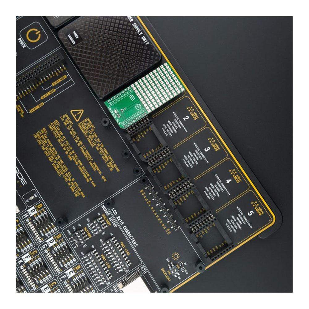
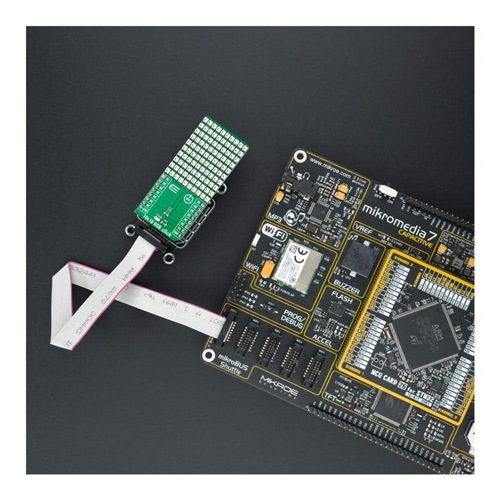
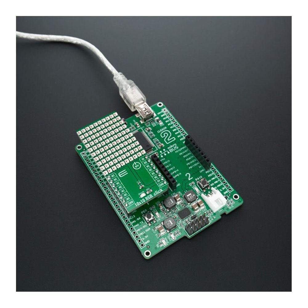
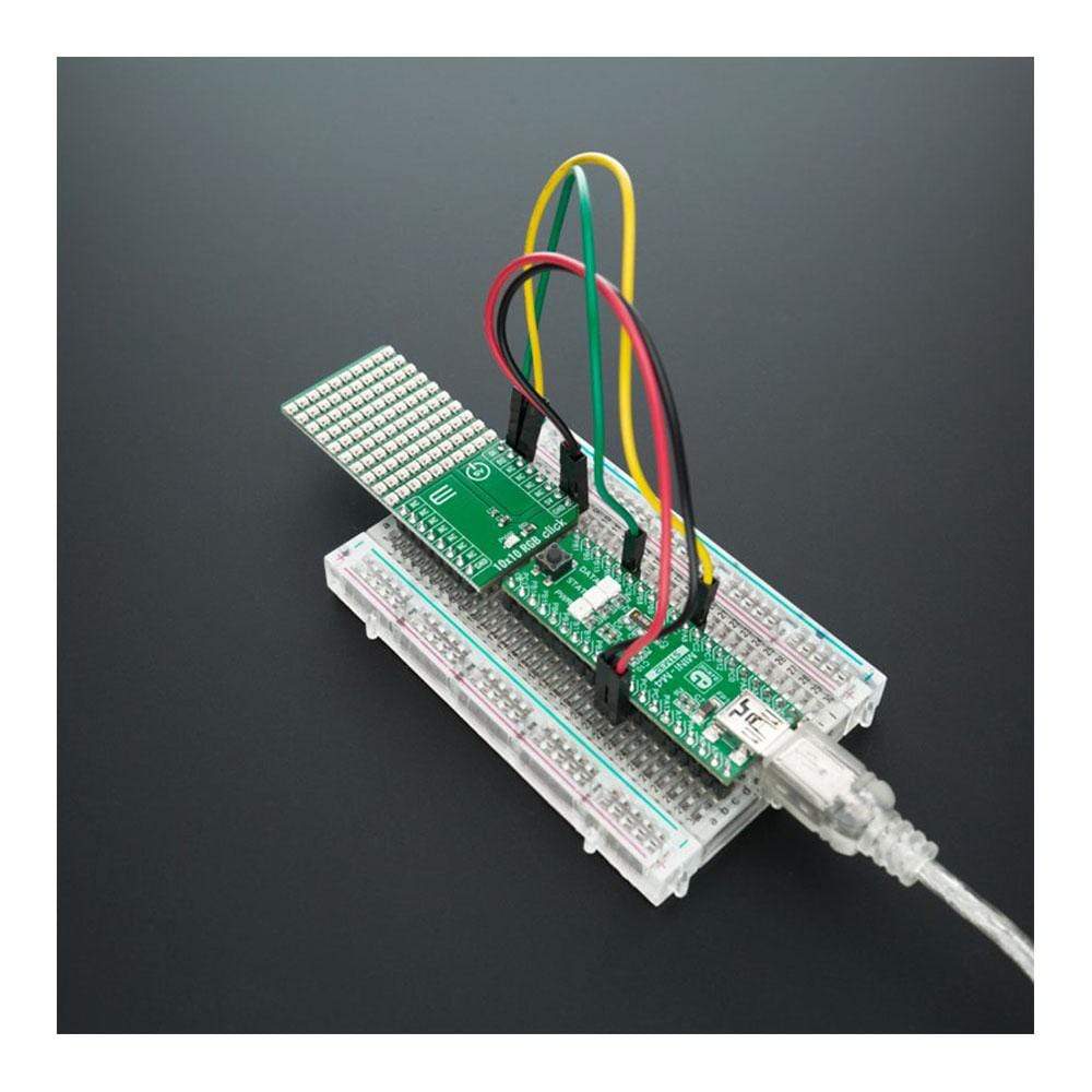
Conçu pour simplifier le développement logiciel, le Click Board™ RGB 10x10 est pris en charge par une bibliothèque compatible mikroSDK qui offre une gamme de fonctions pour une programmation efficace. Ce Click Board™ entièrement testé est prêt à être intégré dans des systèmes équipés d'une prise mikroBUS™, offrant une expérience utilisateur sans tracas.
Transformez vos projets avec le Click Board™ RGB 10x10 et découvrez un monde de possibilités en matière d'affichage visuel et de contrôle de l'éclairage. Idéal pour les passionnés, les amateurs et les professionnels, ce Click Board™ innovant offre fonctionnalité, fiabilité et facilité d'utilisation dans un format compact.
Explorez le potentiel infini du 10x10 RGB Click Board™ et élevez vos projets vers de nouveaux sommets de créativité et de fonctionnalité.
How Does The 10x10 RGB Click Board™ Work?
The WS2812 is an intelligent control LED light source, its exterior adopts the latest MOLDING packaging technology, the control circuit and RGB chips are integrated in a package of 2020 component. Its internal includes intelligent digital port data latch and signal reshaping amplification drive circuit. Also include a precision internal oscillator and a voltage programmable constant current control part, effectively ensuring the pixel point light colour height consistent.
The data transfer protocol use single NZR communication mode. After the pixel power-on reset, the DIN port receive data from controller, the first pixel collect initial 24bit data then sent to the internal data latch, the other data which reshaping by the internal signal reshaping amplification circuit sent to the next cascade pixel through the DO port. After transmission for each pixel, the signal to reduce 24bit. pixel adopt auto reshaping transmit technology, making the pixel cascade number is not limited the signal transmission, only depend on the speed of signal transmission.
RESET time >280μs , it won't cause wrong reset while interruption, it supports the lower frequency and inexpensive MCU.
Refresh Frequency updates to 2KHz, Low Frame Frequency and No Flicker appear in HD Video Camera, it improve excellent display effect.
LED with low driving voltage, environmental protection and energy saving, high brightness, large scattering angle, good consistency, low-power, long life and other advantages. The control chip integrated in LED above becoming more simple circuit, small volume, convenient installation. The 10x10 RGB Click Board™ can be used in many applications, like full-colour module, full colour soft lights a lamp strip, LED decorative lighting, indoor/outdoor LED irregular screen, game machine and amusement equipment etc.
The INT pin of the mikroBUS, which is labelled as DO on this Click Board™, allows cascading of multiple 10x10 RGB Click Board™ devices. It simply routes the data line back to the mikroBUS, allowing it to be re-used for the next 10x10 RGB Click Board™, and so on. The length of the whole chain is limited only by the communication speed, required to scan through all the LED devices, in order to maintain a reasonable refresh speed.
The 10x10 RGB Click Board™ is designed to be operated only with 5V logic level. A proper logic voltage level conversion should be performed before the Click Board™ is used with MCUs with logic levels of 3V3.
SPECIFICATIONS
Type | Optical |
Applications | Full-colour module, Full color soft lights a lamp strip, LED decorative lighting, indoor/outdoor LED irregular screen, game machine and amusement equipment etc. |
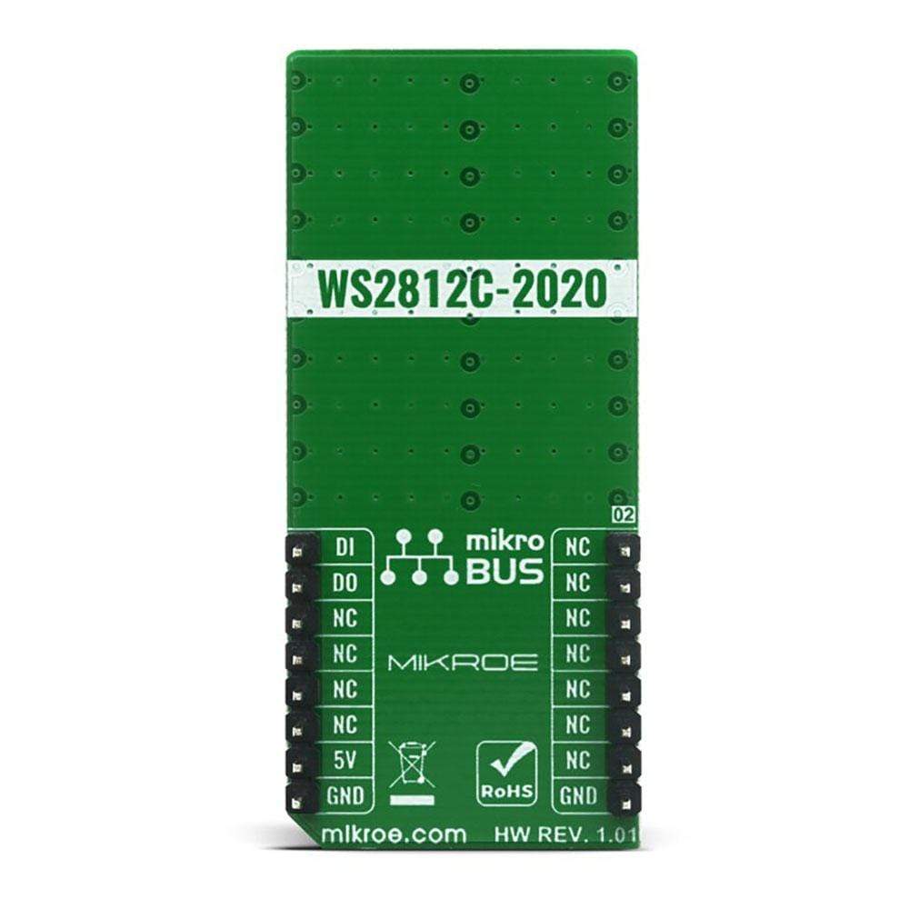
On-board modules | WS2812 intelligent control LED |
Key Features | 256 brightness display, completed 16777216 colour full colour display and scan frequency is of 2KHz, send data speed of 800Kbps, 5mA operating current per channel |
Interface | GPIO |
Compatibility | mikroBUS |
Click Board™ size | L (57.15 x 25.4 mm) |
Input Voltage | 5V |
PINOUT DIAGRAM
This table shows how the pinout on the 10x10 RGB Click Board™ corresponds to the pinout on the mikroBUS socket (the latter shown in the two middle columns).
Notes | Pin | Pin | Notes | ||||
---|---|---|---|---|---|---|---|
NC | 1 | AN | PWM | 16 | DI | Data Input | |
NC | 2 | RST | INT | 15 | DO | Data Output | |
NC | 3 | CS | RX | 14 | NC | ||
NC | 4 | SCK | TX | 13 | NC | ||
NC | 5 | MISO | SCL | 12 | NC | ||
NC | 6 | MOSI | SDA | 11 | NC | ||
NC | 7 | 3.3V | 5V | 10 | 5V | Power Supply | |
Ground | GND | 8 | GND | GND | 9 | GND | Ground |
ONBOARD SETTINGS AND INDICATORS
Label | Name | Default | Description |
---|---|---|---|
LD1 | PWR | - | Power LED Indicator |
JP1-JP4 | COM SEL | Right |
Software Support
We provide a library for the 10x10 RGB Click Board™ on our LibStock page, as well as a demo application (example), developed using MikroElektronika compilers. The demo can run on all the main MikroElektronika development boards.
Library Description
Library contains function for show Image, Byte and String and one demo (rainbow).
Key Functions
void c10x10rgb_setup( void (*logic_one)( void ), void (*logic_zero)( void ) )
- Setup functionvoid c10x10rgb_demo_rainbow ( uint8_t brightness, uint16_t wait_ms )
- Demo rainbowvoid c10x10rgb_display_string ( c10x10rgb_byte_t *data_obj, uint8_t len, uint16_t speed_ms )
- Function for shows string
Example Description
The application is composed of three sections :
- System Initialization - Initializes all necessary GPIO pins
- Application Initialization - Initializes driver inti and setup module
- Application Task - Shows one byte, then scrolls the string, image and rainbow demo.
void application_task ( ) { c10x10rgb_display_byte ( &rgb_data_byte[ 0 ] ); Delay_ms( 1000 ); c10x10rgb_display_byte ( &rgb_data_byte[ 1 ] ); Delay_ms( 1000 ); c10x10rgb_display_byte ( &rgb_data_byte[ 2 ] ); Delay_ms( 2000 ); c10x10rgb_display_string( &scroll_data_obj, scroll_data_len, scroll_speed_ms ); Delay_ms( 1000 ); c10x10rgb_display_image( &MIKROE_IMAGE[ 0 ] ); Delay_ms( 3000 ); c10x10rgb_demo_rainbow( rainbow_brightness, rainbow_speed_ms ); Delay_ms( 1000 ); }
The full application code, and ready to use projects can be found on our LibStock page.
Other mikroE Libraries used in the example:
- GPIO
Additional Notes and Information
Depending on the development board you are using, you may need USB UART Click Board™, USB UART 2 Click Board™ or RS232 Click Board™ to connect to your PC, for development systems with no UART to USB interface available on the board. The terminal available in all MikroElektronika compilers, or any other terminal application of your choice, can be used to read the message.
MIKROSDK
The 10x10 RGB Click Board™ is supported with mikroSDK - MikroElektronika Software Development Kit. To ensure proper operation of mikroSDK compliant Click Board™ demo applications, mikroSDK should be downloaded from the LibStock and installed for the compiler you are using.
Carte à clic RVB 10x10
Frequently Asked Questions
Have a Question?
Be the first to ask a question about this.