


Mikroelektronika d.o.o.
Tableau à clic TMR Mix-Sens
Tableau à clic TMR Mix-Sens
SKU: MIKROE-4106
Impossible de charger la disponibilité du service de retrait
Overview
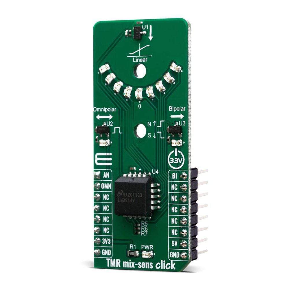
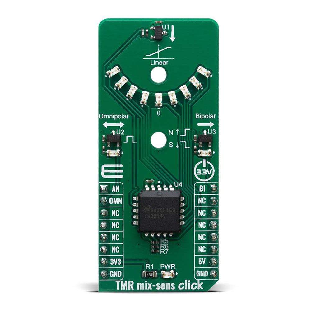
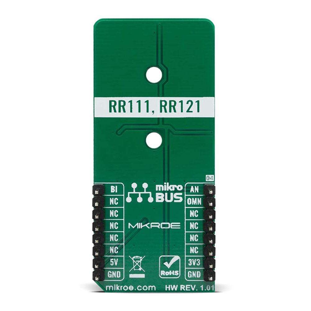
The TMR mix-sens Click Board™ is equipped with the TMR digital push-pull and analogue magnetic sensors, as well as the intensity of the magnetic field indicator. The TMR mix-sens Click Board™ has three types of magnetic field sensors: Two digital and one analogue sensor. The digital sensors are the RR121-1A23-311 which has an omnipolar polarity response, and the RR121-3C63-311 which has a bipolar polarity response. The analogue sensor is the RR111-1DC2-331, which outputs a voltage that is proportional to the magnetic field. The board also has an LM3914 voltage level indicator, which takes the output voltage of the RR111-1DC2-331 sensor and uses it to light a series of LEDs to indicate the level of magnetic field seen by the sensor. All sensor outputs can be accessed through mikroBUS I/O or analogue pins, also they are visually represented over onboard LED's. This board can be used for evaluation of the TMR sensors as well as for testing applications which are requiring low power wake up functionality.
The TMR mix-sens Click Board™ is supported by a mikroSDK compliant library, which includes functions that simplify software development. This Click Board™ comes as a fully tested product, ready to be used on a system equipped with the mikroBUS™ socket.
Downloads
Le TMR mix-sens Click Board™ est équipé de capteurs magnétiques numériques push-pull et analogiques TMR, ainsi que de l'indicateur d'intensité du champ magnétique. Le TMR mix-sens Click Board™ possède trois types de capteurs de champ magnétique : deux capteurs numériques et un capteur analogique. Les capteurs numériques sont le RR121-1A23-311 qui a une réponse de polarité omnipolaire et le RR121-3C63-311 qui a une réponse de polarité bipolaire. Le capteur analogique est le RR111-1DC2-331, qui produit une tension proportionnelle au champ magnétique. La carte dispose également d'un indicateur de niveau de tension LM3914, qui prend la tension de sortie du capteur RR111-1DC2-331 et l'utilise pour allumer une série de LED pour indiquer le niveau de champ magnétique vu par le capteur. Toutes les sorties de capteur sont accessibles via les E/S mikroBUS ou les broches analogiques, elles sont également représentées visuellement sur des LED intégrées. Cette carte peut être utilisée pour l'évaluation des capteurs TMR ainsi que pour tester des applications nécessitant une fonctionnalité de réveil à faible consommation d'énergie.
Le TMR mix-sens Click Board™ est pris en charge par une bibliothèque compatible mikroSDK, qui comprend des fonctions qui simplifient le développement logiciel. Ce Click Board™ est un produit entièrement testé, prêt à être utilisé sur un système équipé du socket mikroBUS™.
| General Information | |
|---|---|
Part Number (SKU) |
MIKROE-4106
|
Manufacturer |
|
| Physical and Mechanical | |
Weight |
0.02 kg
|
| Other | |
EAN |
8606018717392
|
Frequently Asked Questions
Have a Question?
Be the first to ask a question about this.