


Mikroelektronika d.o.o.
Carte à clic CAN FD 2
Carte à clic CAN FD 2
SKU: MIKROE-4062
Impossible de charger la disponibilité du service de retrait


Overview
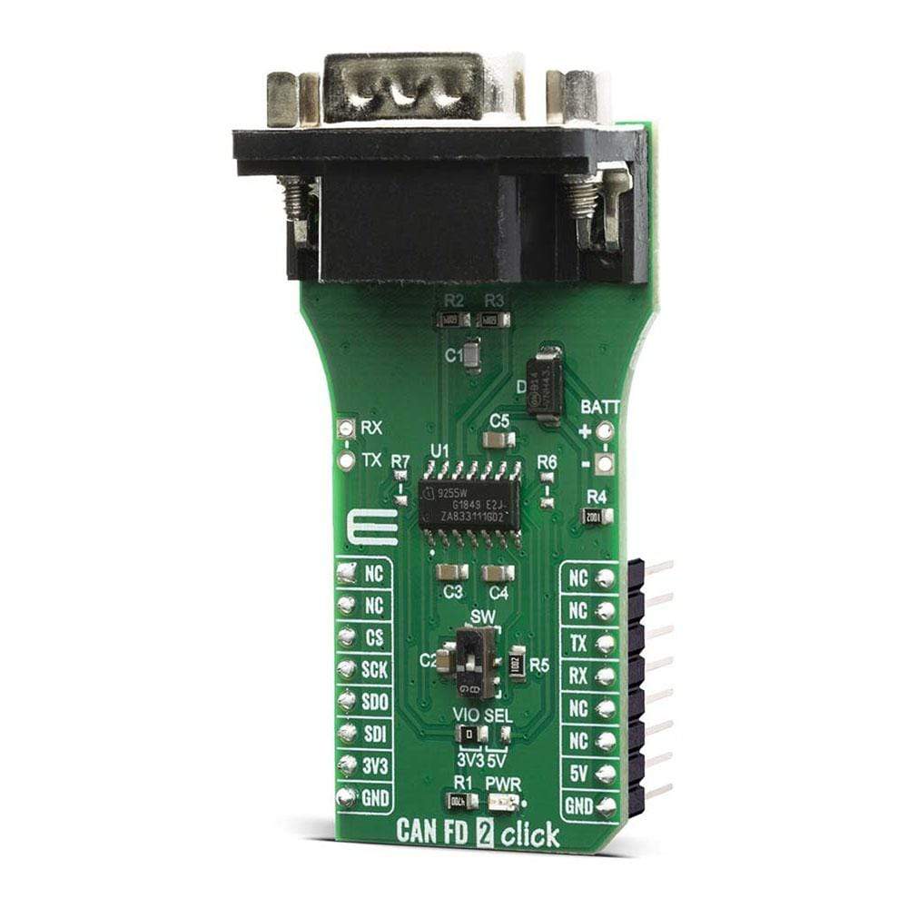
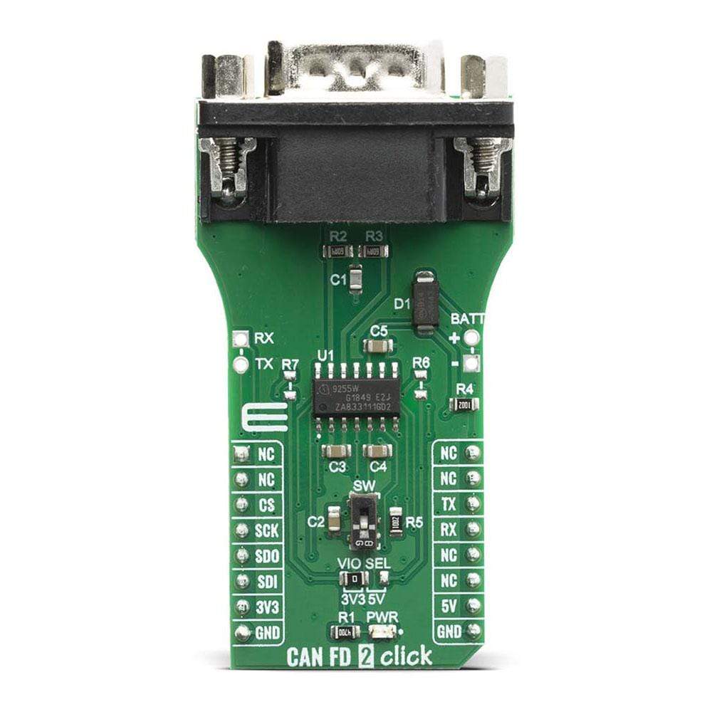
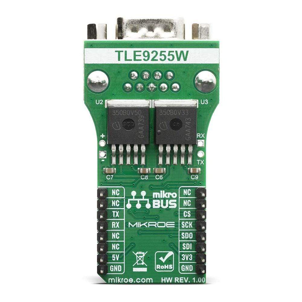
The CAN FD 2 Click Board™ is an HS CAN transceiver add on board, suitable for the evaluation of the TLE9255W CAN network transceiver from Infineon. The transceiver itself drives the signals to the CAN bus and protects the microcontroller from interference generated within the CAN network. Based on the high symmetry of the CANH and CANL signals, the TLE9255W provides a very low level of electromagnetic emission within a wide frequency range, allowing the operation of the TLE9255W without a common mode choke in automotive and industrial applications.
Downloads
Le CAN FD 2 Click Board™ est une carte d'extension d'émetteur-récepteur CAN HS, adaptée à l'évaluation de l'émetteur-récepteur de réseau CAN TLE9255W d'Infineon. L'émetteur-récepteur lui-même transmet les signaux au bus CAN et protège le microcontrôleur des interférences générées au sein du réseau CAN. Basé sur la symétrie élevée des signaux CANH et CANL, le TLE9255W fournit un très faible niveau d'émission électromagnétique dans une large gamme de fréquences, permettant le fonctionnement du TLE9255W sans starter de mode commun dans les applications automobiles et industrielles.
| General Information | |
|---|---|
Part Number (SKU) |
MIKROE-4062
|
Manufacturer |
|
| Physical and Mechanical | |
Weight |
0.02 kg
|
| Other | |
EAN |
8606018717194
|
Frequently Asked Questions
Have a Question?
Be the first to ask a question about this.