


Mikroelektronika d.o.o.
Planche à clic Balancer 2
Planche à clic Balancer 2
SKU: MIKROE-4058
Impossible de charger la disponibilité du service de retrait


Overview
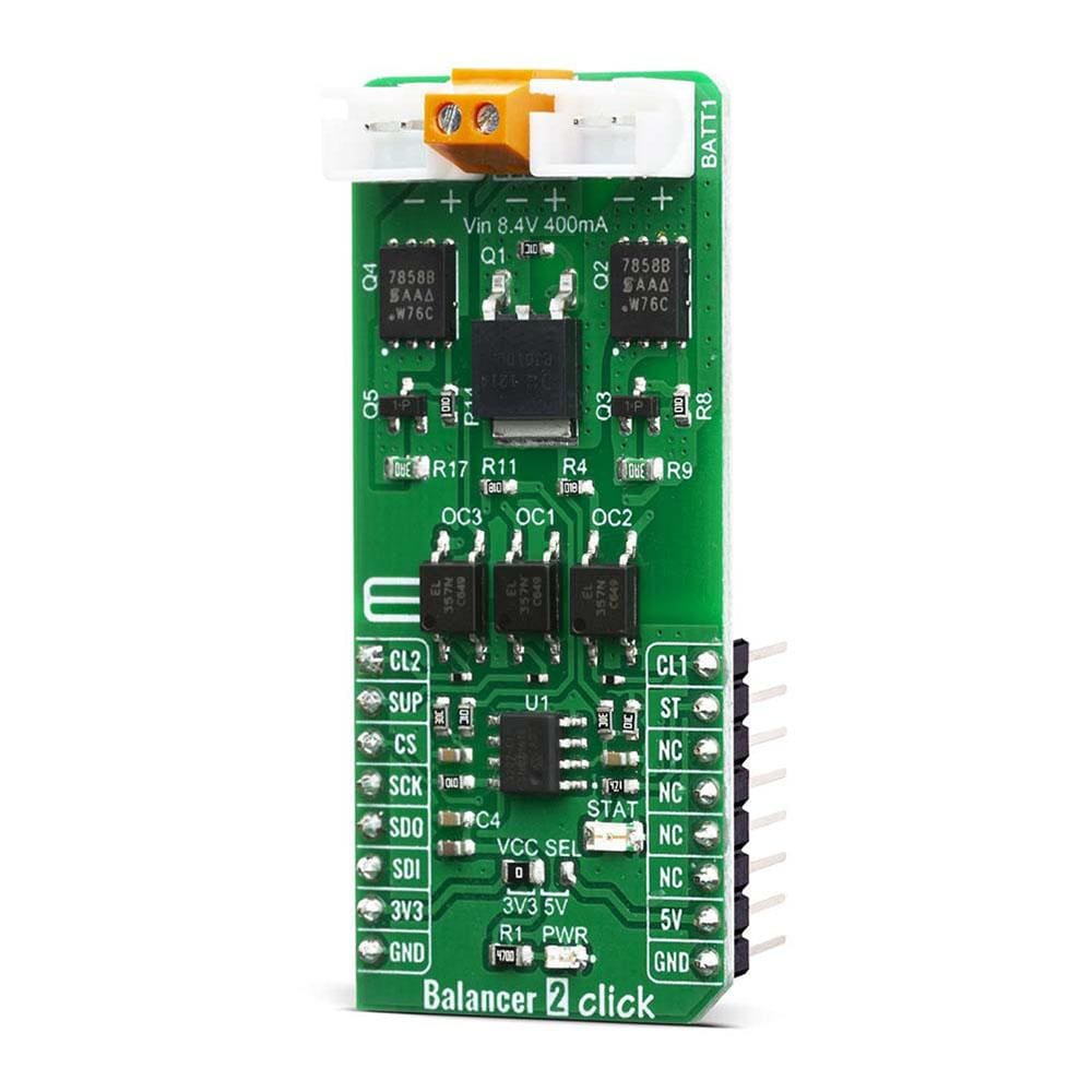
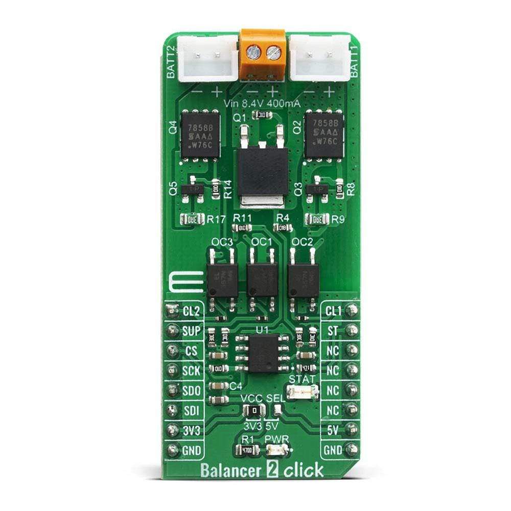
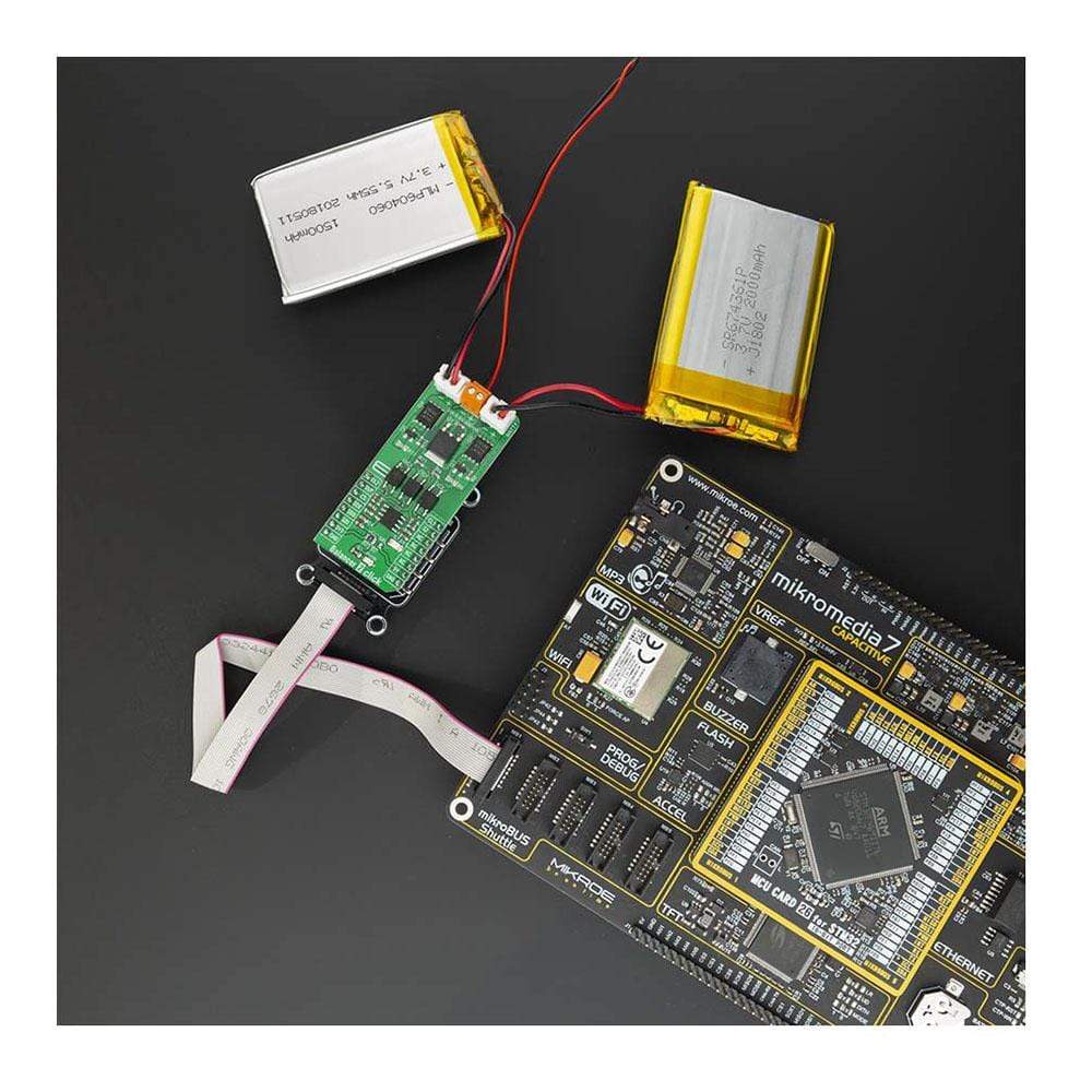
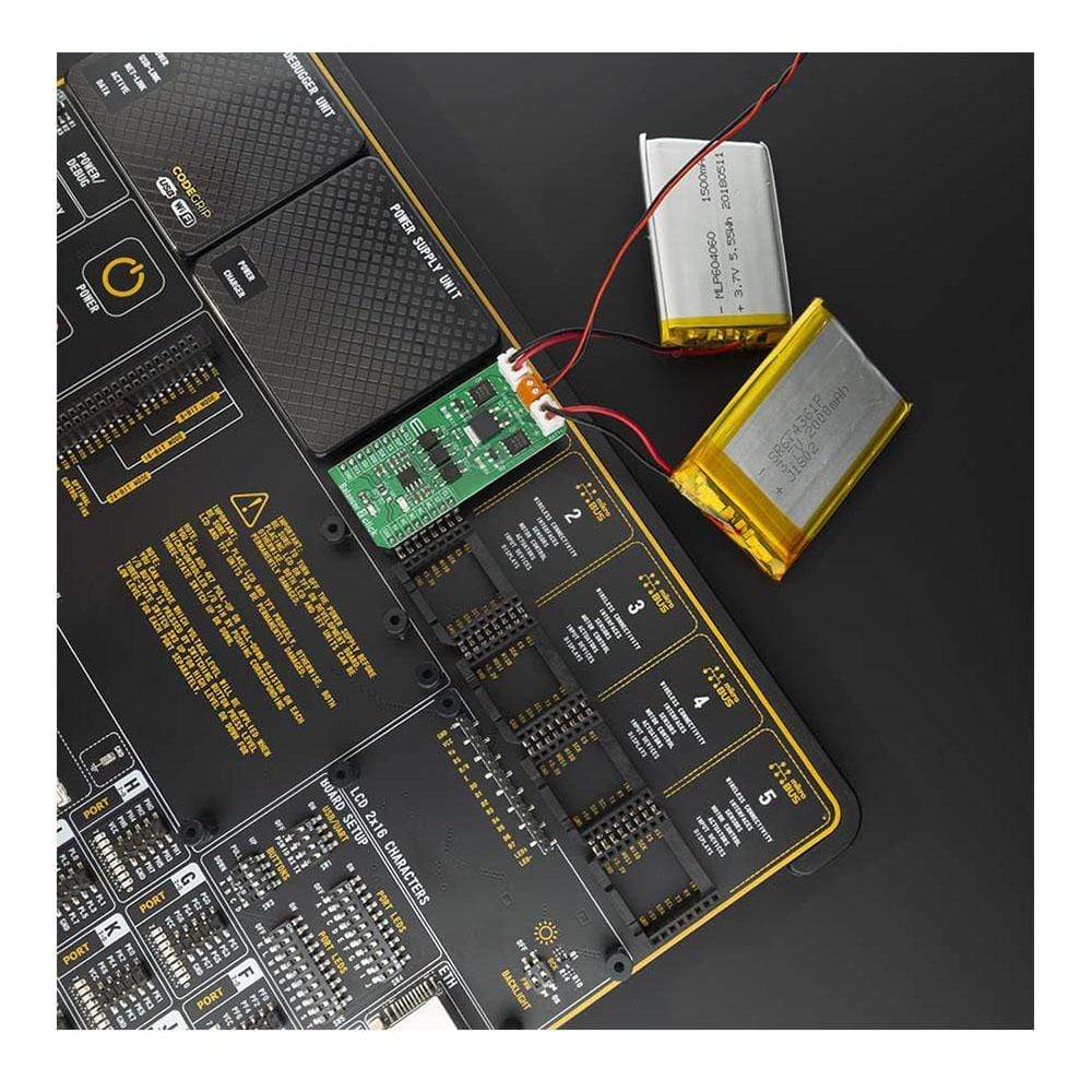
The Balancer 2 Click Board™ is an overvoltage protection device for a 2-series cell lithium-ion battery. Click contains two separate overvoltage battery detection circuits and automatic cell imbalance correction. It can be used for various applications, power tools, portable equipment, and instrumentation, to energy storage systems (ESS), while providing the output voltage at the same time. By utilizing an externally connected power supply, it can charge 2-cell Li-Ion batteries.
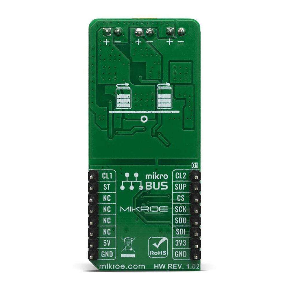
The Balancer 2 Click Board™ is supported by the mikroSDK compliant library, which includes functions that simplify software development. The Click Board™ comes as a fully tested product, ready to be used on a system equipped with mikroBUS™.
Downloads
Le Balancer 2 Click Board™ est un dispositif de protection contre les surtensions pour une batterie lithium-ion à 2 cellules en série. Click contient deux circuits de détection de surtension de batterie distincts et une correction automatique du déséquilibre des cellules. Il peut être utilisé pour diverses applications, outils électriques, équipements portables et instrumentation, systèmes de stockage d'énergie (ESS), tout en fournissant la tension de sortie en même temps. En utilisant une alimentation connectée en externe, il peut charger des batteries Li-Ion à 2 cellules.
Le Balancer 2 Click Board™ est pris en charge par la bibliothèque compatible mikroSDK, qui comprend des fonctions qui simplifient le développement logiciel. Le Click Board™ est un produit entièrement testé, prêt à être utilisé sur un système équipé de mikroBUS™.
| General Information | |
|---|---|
Part Number (SKU) |
MIKROE-4058
|
Manufacturer |
|
| Physical and Mechanical | |
Weight |
0.022 kg
|
| Other | |
EAN |
8606018717156
|
Frequently Asked Questions
Have a Question?
Be the first to ask a question about this.