


Mikroelektronika d.o.o.
Adaptateur Monarch Click Board
Adaptateur Monarch Click Board
SKU: MIKROE-4057
Impossible de charger la disponibilité du service de retrait

Overview
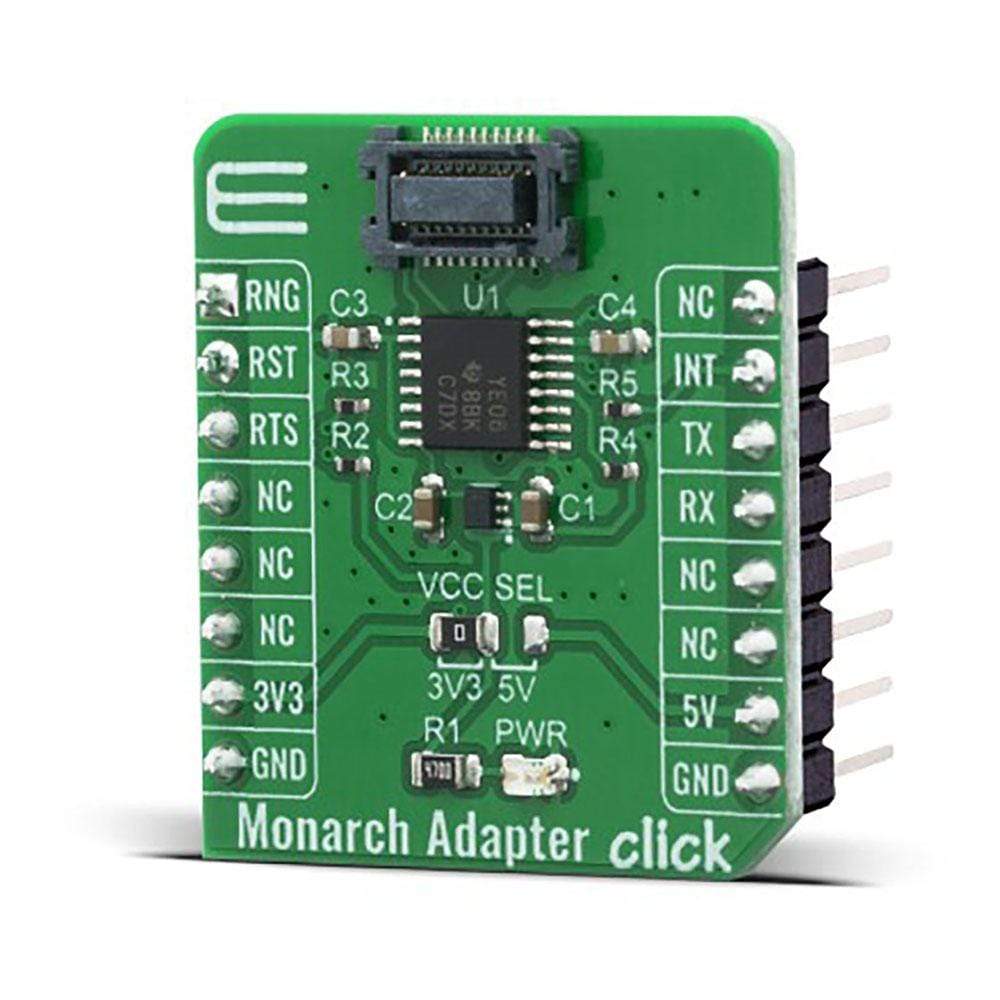
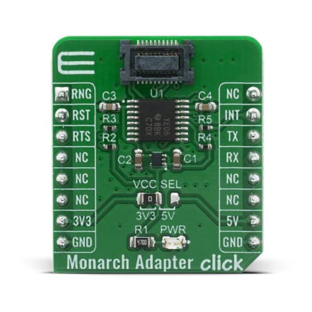
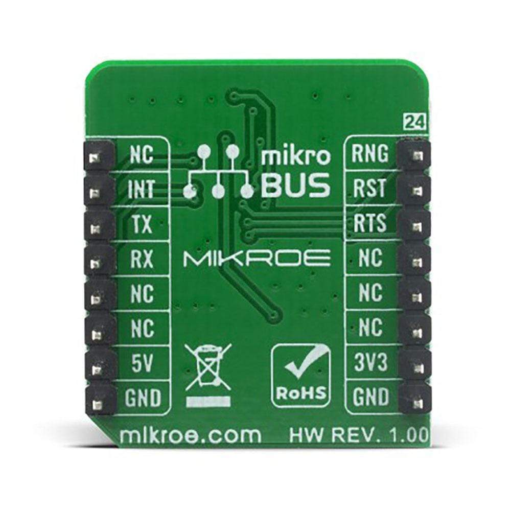
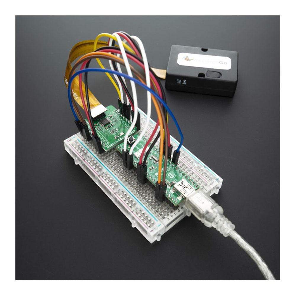
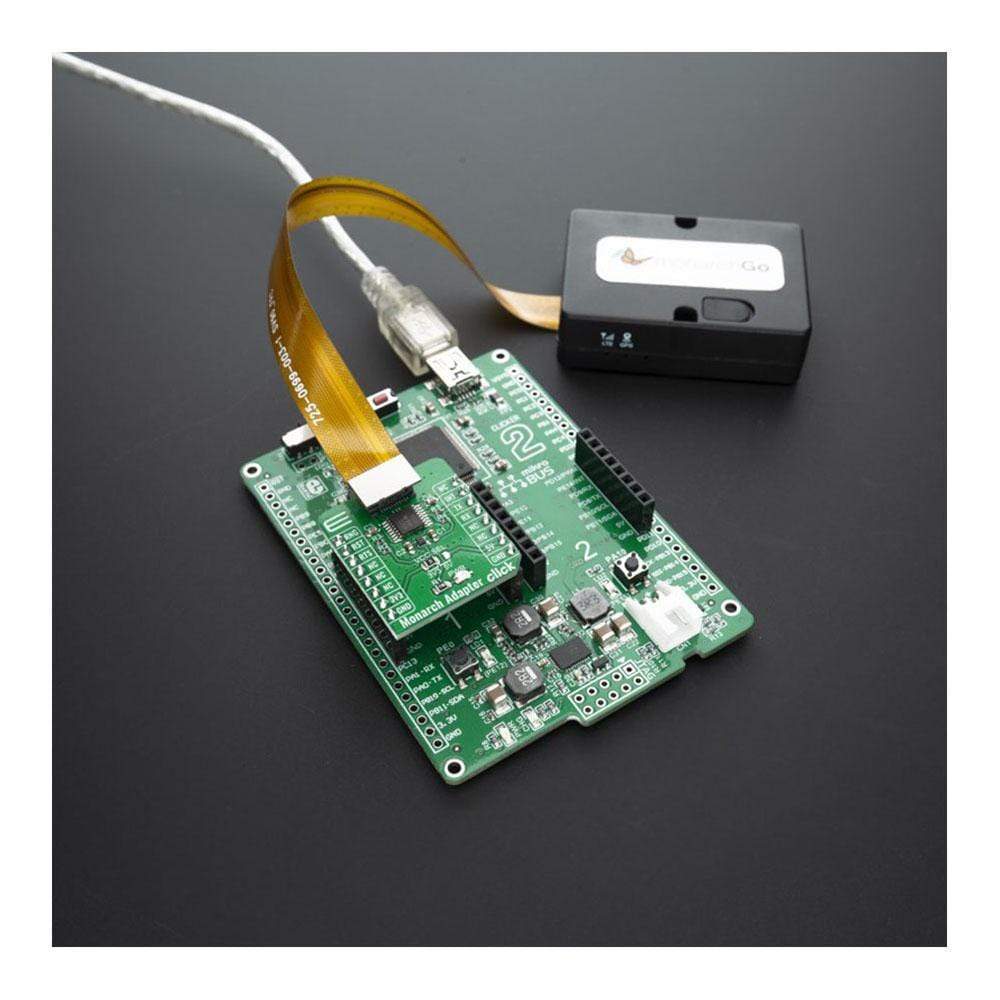
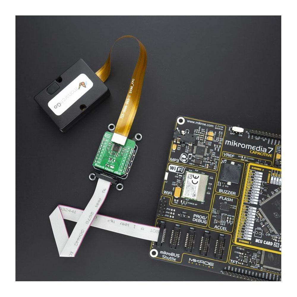
The Monarch Adapter Click Board™ is used to connect compatible Monarch Go LTE-M modems from Sequans to your development board or prototype device. This Click adapter provides a connection to the cloud server with AT commands. The Monarch Go LTE-M modem component with embedded antenna is perfectly suited for a broad range of IoT applications, including telemetry, vending machines, agriculture sensor applications, asset and transportation trackers, hardware tools, and home security monitoring applications.
The Monarch Adapter Click Board™ is supported by a mikroSDK compliant library, which includes functions that simplify software development. This Click Board™ comes as a fully tested product, ready to be used on a system equipped with the mikroBUS™ socket.
Downloads
L' adaptateur Click Board™ Monarch est utilisé pour connecter les modems LTE-M Monarch Go compatibles de Sequans à votre carte de développement ou à votre prototype. Cet adaptateur Click fournit une connexion au serveur cloud avec des commandes AT. Le composant modem LTE-M Monarch Go avec antenne intégrée est parfaitement adapté à une large gamme d'applications IoT, notamment la télémétrie, les distributeurs automatiques, les applications de capteurs agricoles, les dispositifs de suivi des actifs et des transports, les outils matériels et les applications de surveillance de la sécurité domestique.
Le Monarch Adapter Click Board™ est pris en charge par une bibliothèque compatible mikroSDK, qui comprend des fonctions qui simplifient le développement logiciel. Ce Click Board™ est un produit entièrement testé, prêt à être utilisé sur un système équipé du socket mikroBUS™ .
| General Information | |
|---|---|
Part Number (SKU) |
MIKROE-4057
|
Manufacturer |
|
| Physical and Mechanical | |
Weight |
0.02 kg
|
| Other | |
EAN |
8606018717149
|
Frequently Asked Questions
Have a Question?
Be the first to ask a question about this.