


Mikroelektronika d.o.o.
Carte Click pour cellule de charge 2
Carte Click pour cellule de charge 2
SKU: MIKROE-4047
Impossible de charger la disponibilité du service de retrait


Overview
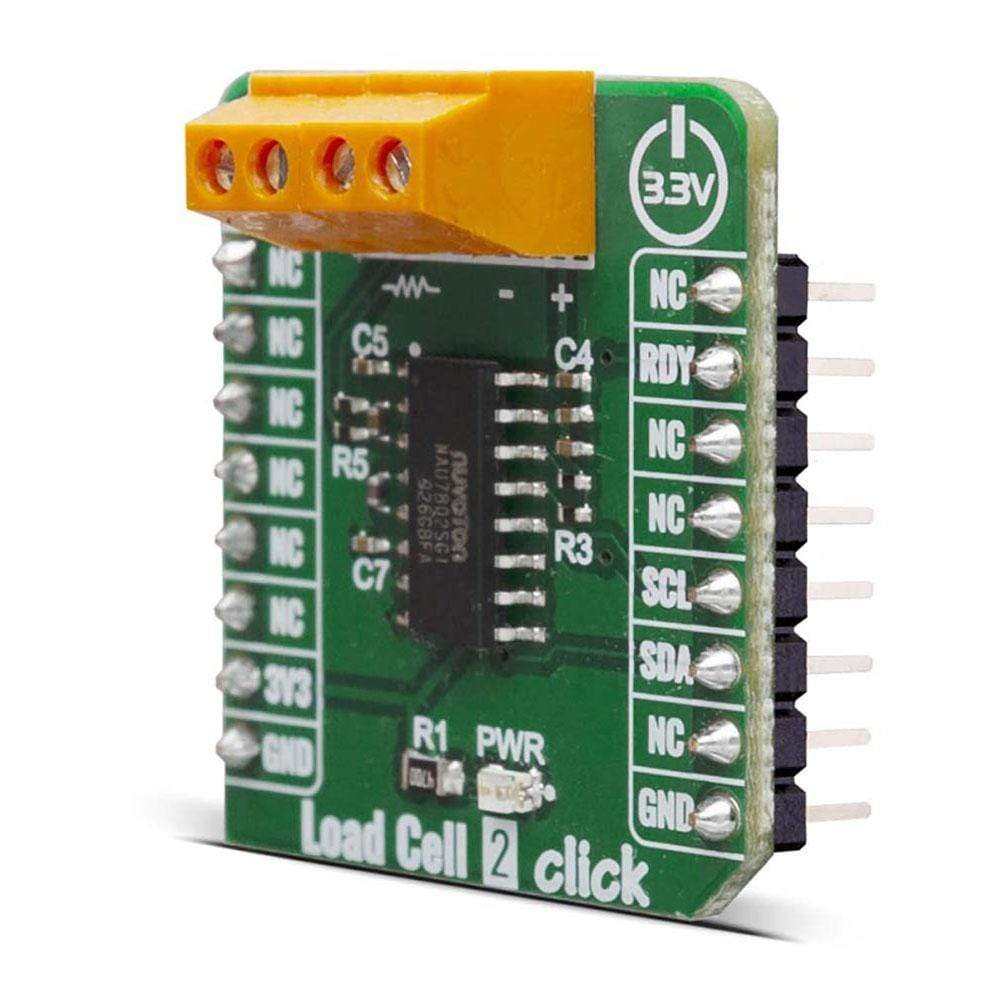
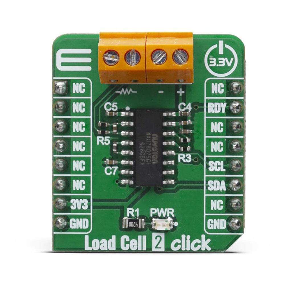
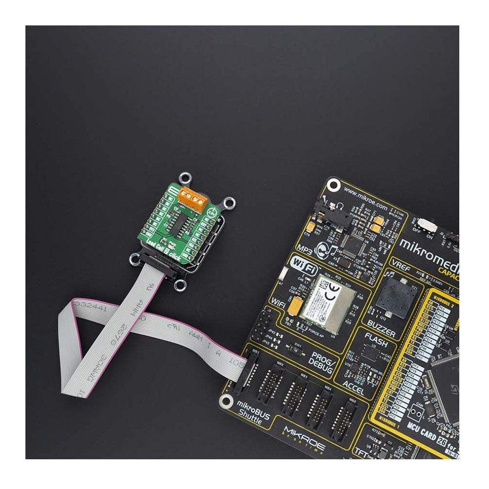
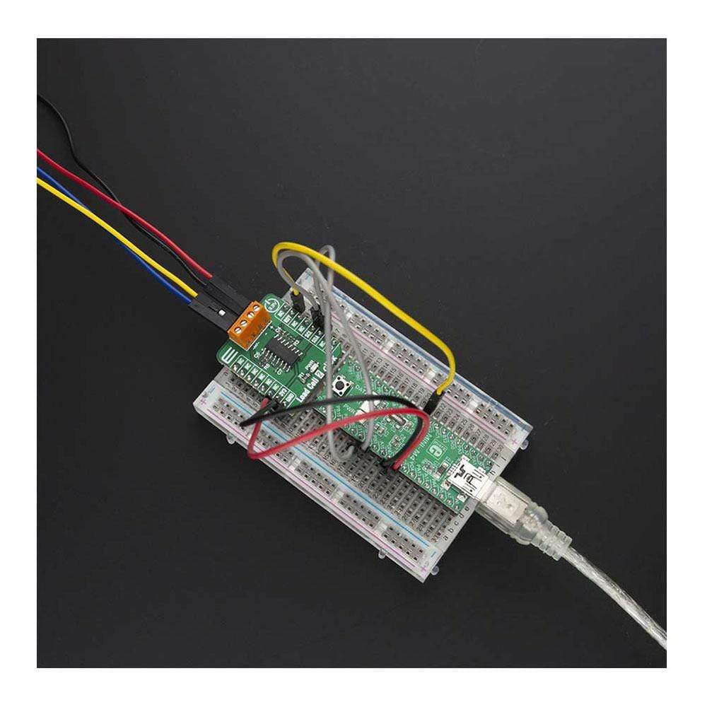
The Load Cell 2 Click Board™ is a weight measurement click that utilizes a load cell element, in order to precisely measure the weight of an object. The Load Cell 2 Click can be used with the strain gauge type of load cells with external differential reference voltage range from 0.1V to 5V. The strain gauge load cell is typically a circuit made of four strain gauges, connected in the Wheatstone bridge configuration. Very small voltage changes need to be accurately detected and converted into a digital form. The Load Cell 2 Click is based around the NAU7802, which is a 24-bit analog-to-digital converter, operated via a simple I2C command, from Nuvoton. This sensor has many features that make it a perfect solution for small designs. One of these features is certainly its high level of integration that allows a minimal number of external components.
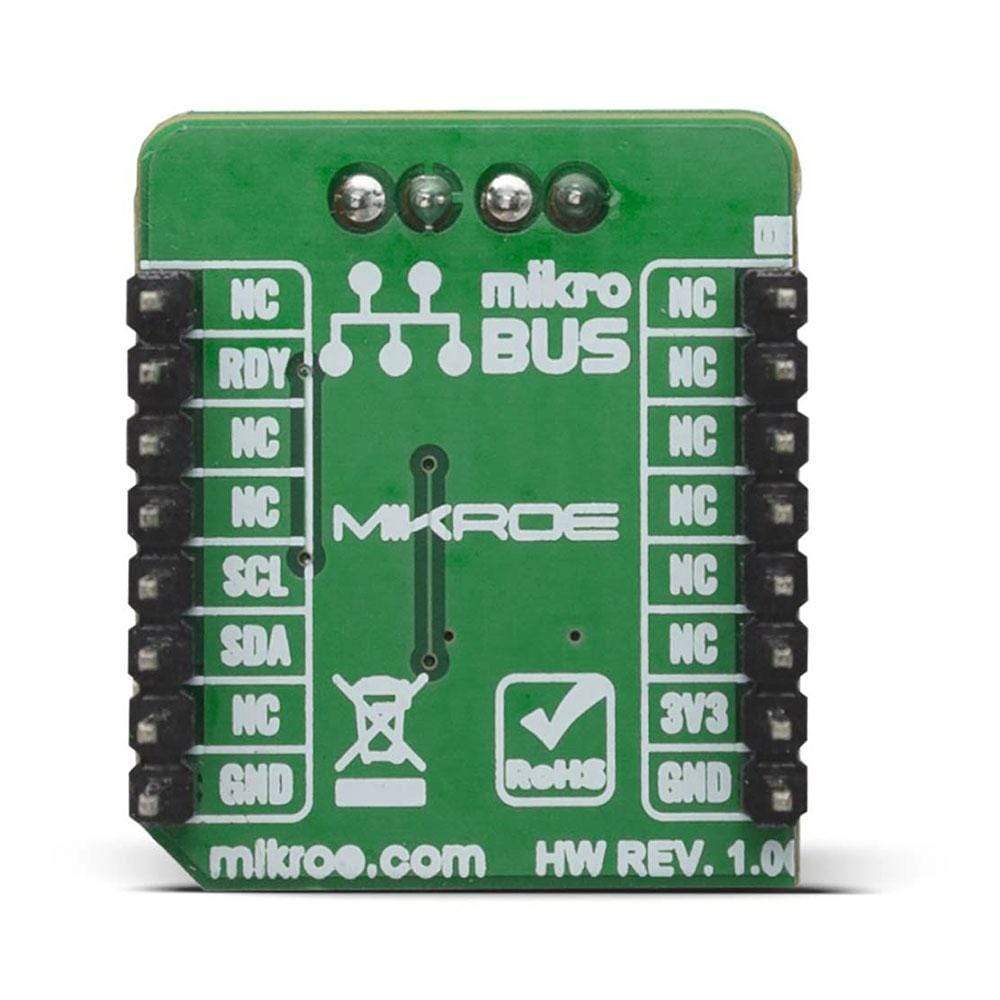
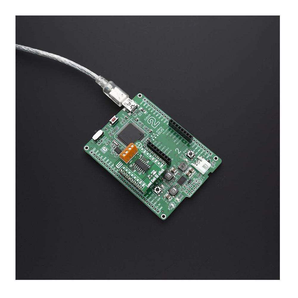
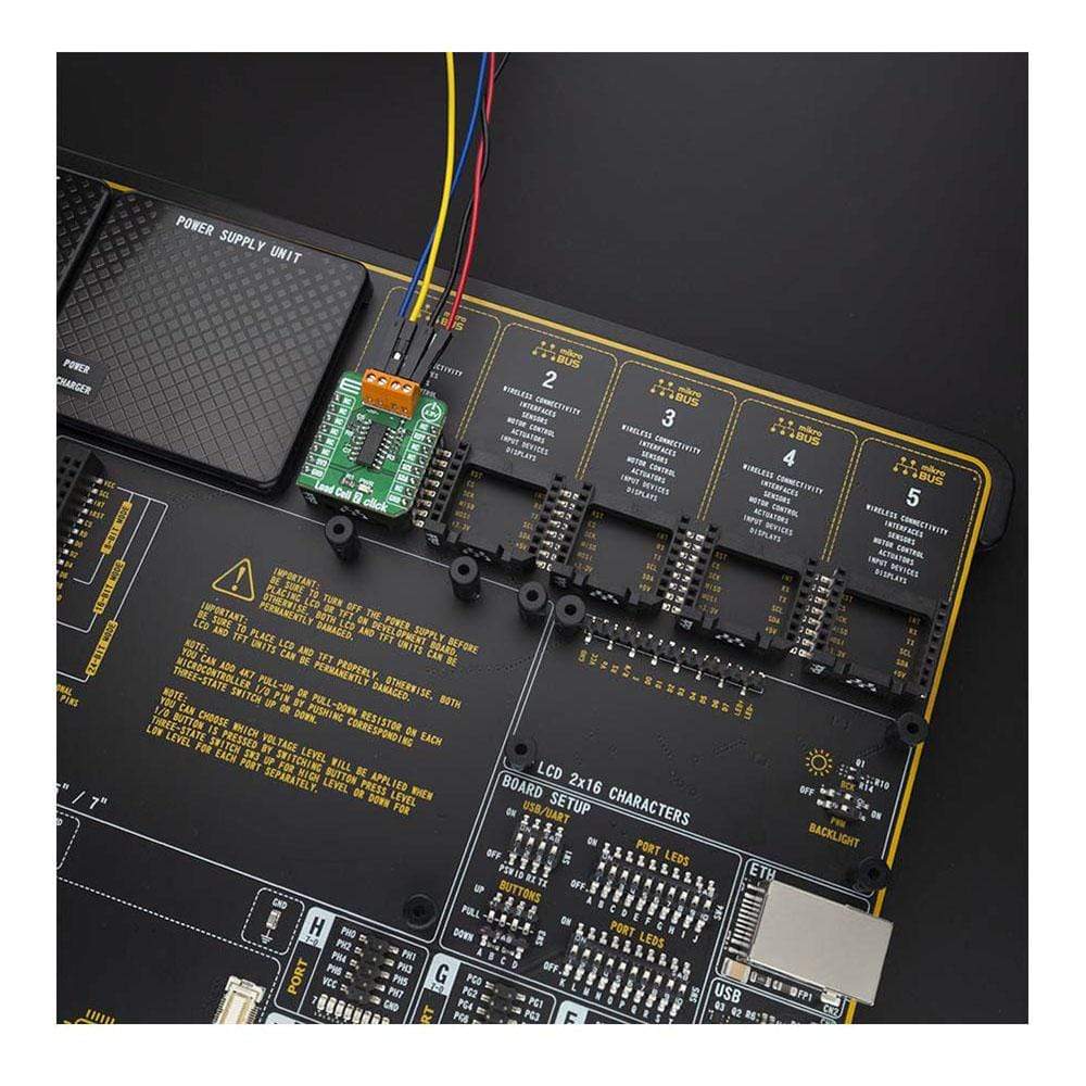
The Load Cell 2 Click Board™ is supported by a mikroSDK compliant library, which includes functions that simplify software development. This Click Board™ comes as a fully tested product, ready to be used on a system equipped with the mikroBUS™ socket.
Downloads
Le Load Cell 2 Click Board™ est un click de mesure de poids qui utilise un élément de cellule de charge, afin de mesurer avec précision le poids d'un objet. Le Load Cell 2 Click peut être utilisé avec les cellules de charge de type jauge de contrainte avec une plage de tension de référence différentielle externe de 0,1 V à 5 V. La cellule de charge à jauge de contrainte est généralement un circuit composé de quatre jauges de contrainte, connectées dans la configuration du pont de Wheatstone. De très petites variations de tension doivent être détectées avec précision et converties sous forme numérique. Le Load Cell 2 Click est basé sur le NAU7802, qui est un convertisseur analogique-numérique 24 bits, actionné via une simple commande I2C, de Nuvoton. Ce capteur possède de nombreuses fonctionnalités qui en font une solution parfaite pour les petites conceptions. L'une de ces caractéristiques est certainement son haut niveau d'intégration qui permet un nombre minimal de composants externes.
La carte Click Board™ Load Cell 2 est prise en charge par une bibliothèque compatible mikroSDK, qui comprend des fonctions qui simplifient le développement logiciel. Cette carte Click Board™ est un produit entièrement testé, prêt à être utilisé sur un système équipé de la prise mikroBUS™.
| General Information | |
|---|---|
Part Number (SKU) |
MIKROE-4047
|
Manufacturer |
|
| Physical and Mechanical | |
Weight |
0.018 kg
|
| Other | |
EAN |
8606018717118
|
Frequently Asked Questions
Have a Question?
Be the first to ask a question about this.