


Mikroelektronika d.o.o.
Carte à clic CAN FD 3
Carte à clic CAN FD 3
SKU: MIKROE-3992
Impossible de charger la disponibilité du service de retrait

Overview
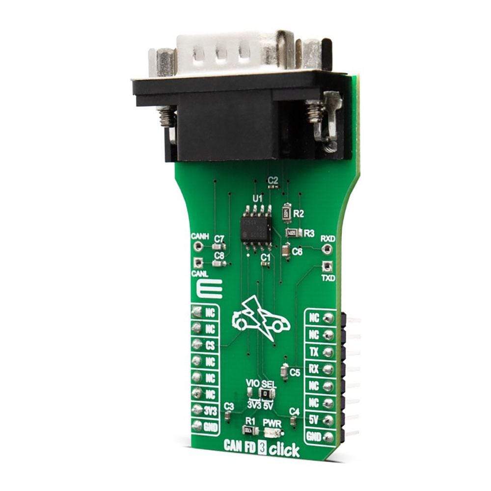
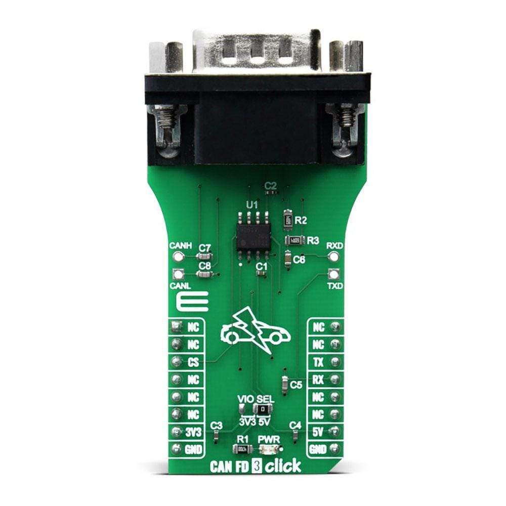
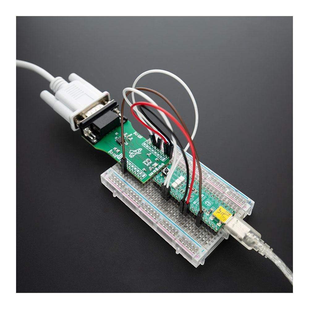
The CAN FD 3 Click Board™ is an add-on board based on TLE9251V CAN network transceiver, designed for HS CAN network up to 5 Mbit/s in automotive and industrial applications. As an interface between the physical bus layer and the CAN protocol controller, the TLE9251V drives the signals to the bus and protects the microcontroller against interferences generated within the network. Given all the features its components offer, the CAN FD Click is best used for infotainment applications, gateway modules, body control modules (BCM) or engine control units (ECUs).
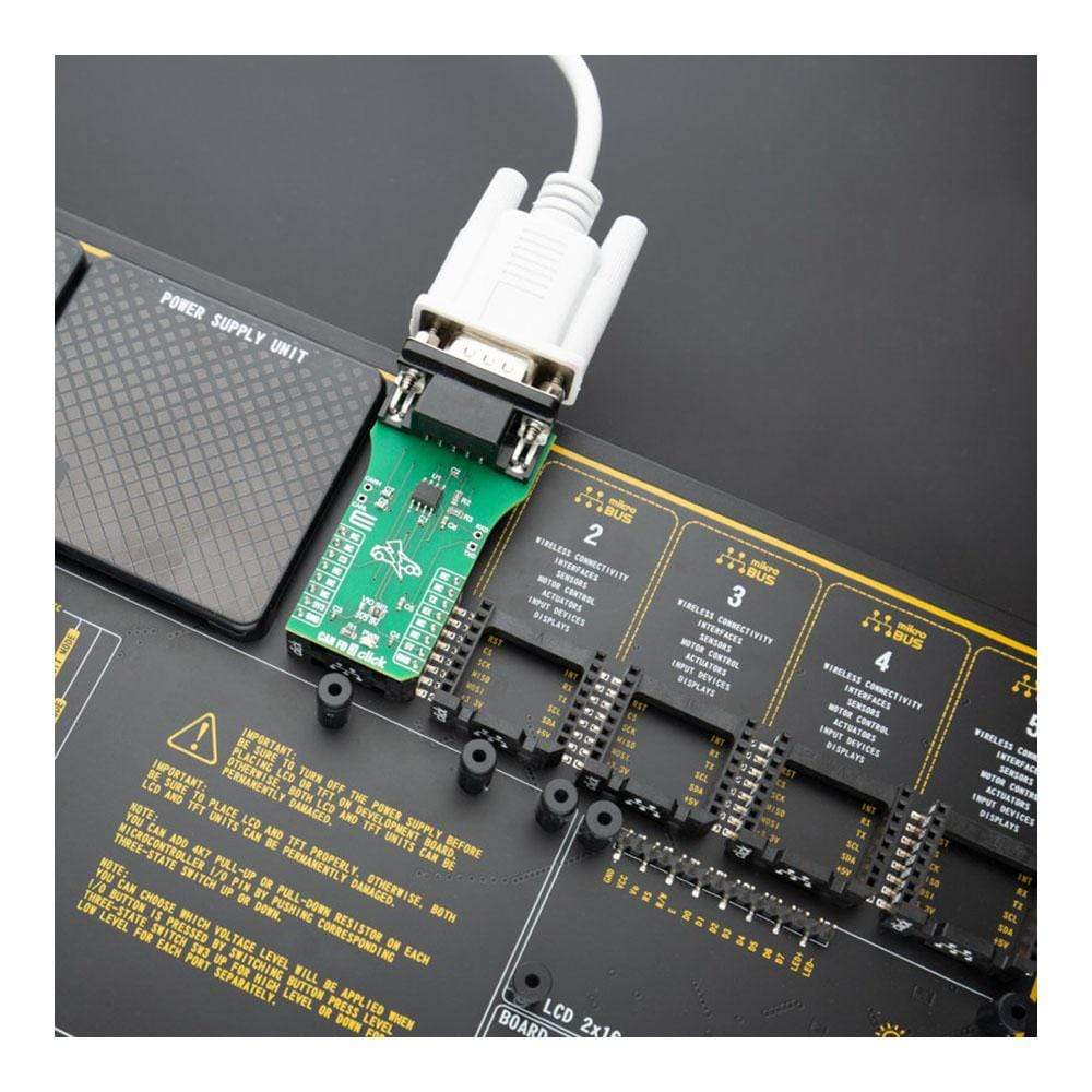
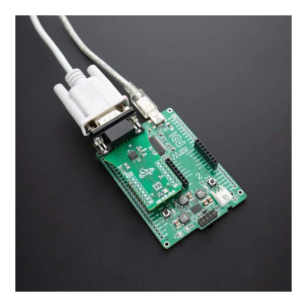
The CAN FD 3 Click Board™ is supported by a mikroSDK compliant library, which includes functions that simplify software development. This Click Board™ comes as a fully tested product, ready to be used on a system equipped with the mikroBUS™ socket.
Downloads
La carte CAN FD 3 Click Board™ est une carte complémentaire basée sur l'émetteur-récepteur réseau CAN TLE9251V, conçue pour les réseaux CAN HS jusqu'à 5 Mbit/s dans les applications automobiles et industrielles. En tant qu'interface entre la couche de bus physique et le contrôleur de protocole CAN, le TLE9251V transmet les signaux au bus et protège le microcontrôleur contre les interférences générées au sein du réseau. Compte tenu de toutes les fonctionnalités offertes par ses composants, la carte CAN FD Click est particulièrement adaptée aux applications d'infodivertissement, aux modules de passerelle, aux modules de contrôle de carrosserie (BCM) ou aux unités de contrôle moteur (ECU).
La carte Click Board™ CAN FD 3 est prise en charge par une bibliothèque compatible mikroSDK, qui comprend des fonctions qui simplifient le développement logiciel. Cette carte Click Board™ est un produit entièrement testé, prêt à être utilisé sur un système équipé de la prise mikroBUS™.
| General Information | |
|---|---|
Part Number (SKU) |
MIKROE-3992
|
Manufacturer |
|
| Physical and Mechanical | |
Weight |
0.026 kg
|
| Other | |
EAN |
8606018718436
|
Frequently Asked Questions
Have a Question?
Be the first to ask a question about this.