


Mikroelektronika d.o.o.
Carte de clic pour moteur à courant continu 14
Carte de clic pour moteur à courant continu 14
SKU: MIKROE-3982
Impossible de charger la disponibilité du service de retrait

Overview
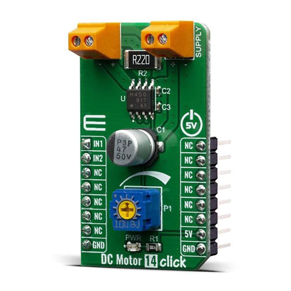
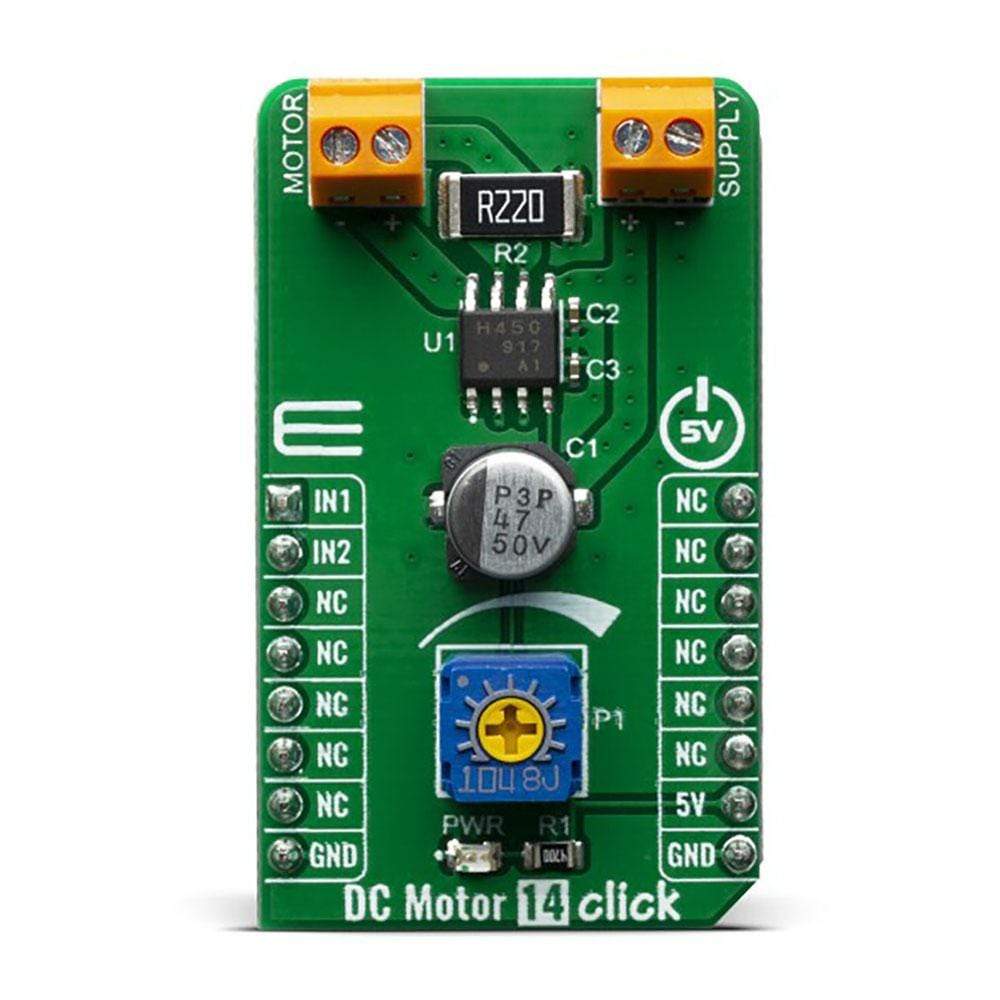
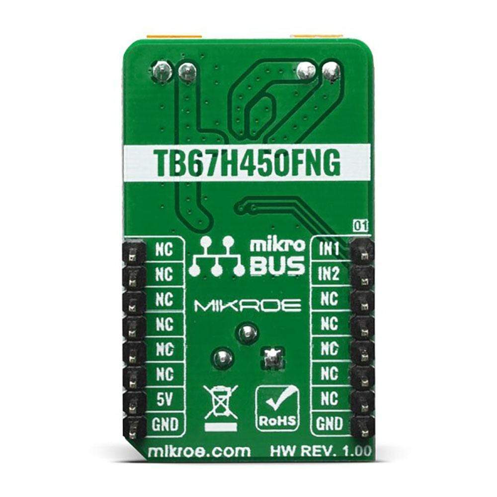
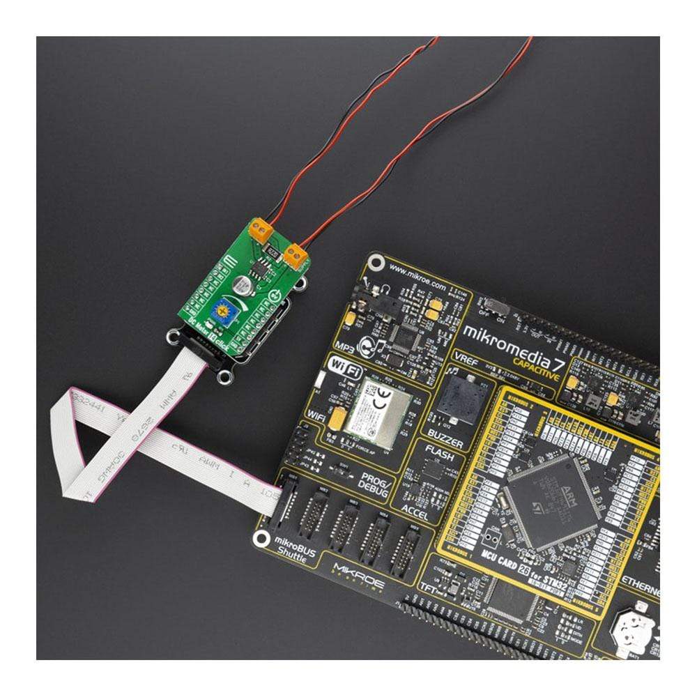
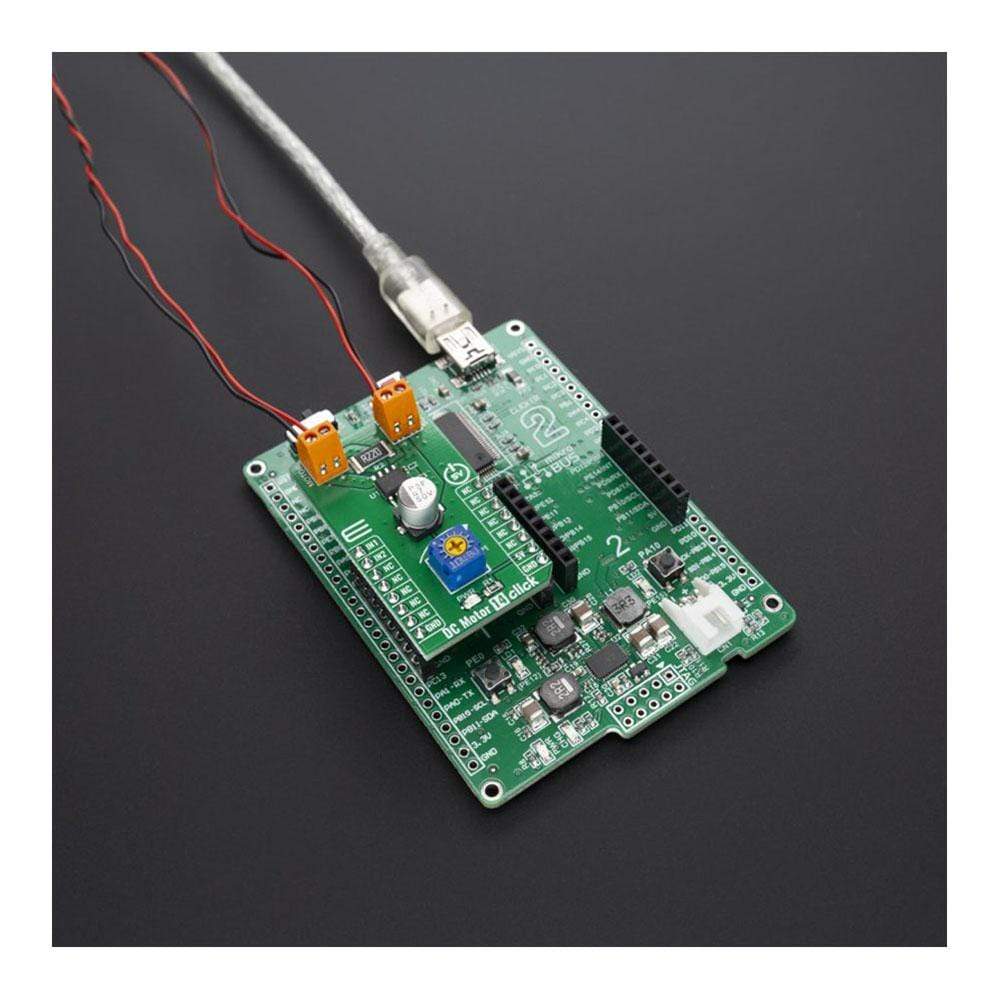
The DC Motor 14 Click Board™ is a PWM chopper type brushed DC motor driver, labelled as TB67H450FNG. This IC includes one channel of motor output block, using a wide range of supply voltages while delivering reasonably high current to the connected DC motors. Low ON-resistance MOSFETs and a PWM control help the TB67H450FNG exhibit lower heat generation thus efficient motor drive. Furthermore, the TB67H450FNG has two inputs, IN1 and IN2, which allow for the selection of the four operation modes; forward (clockwise), reverse (counter-clockwise), short break, and stop modes.
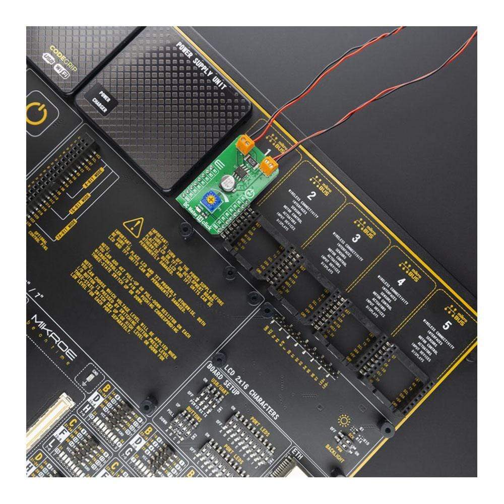
The DC Motor 14 Click Board™ is supported by the mikroSDK compliant library, which includes functions that simplify software development. The Click Board™ comes as a fully tested product, ready to be used on a system equipped with mikroBUS™.
Downloads
Le moteur à courant continu 14 Click Board™ est un pilote de moteur à courant continu à balais de type hacheur PWM, étiqueté TB67H450FNG. Ce circuit intégré comprend un canal de bloc de sortie moteur, utilisant une large gamme de tensions d'alimentation tout en fournissant un courant raisonnablement élevé aux moteurs à courant continu connectés. Les MOSFET à faible résistance à l'état passant et un contrôle PWM aident le TB67H450FNG à produire moins de chaleur, ce qui permet un entraînement efficace du moteur. De plus, le TB67H450FNG dispose de deux entrées, IN1 et IN2, qui permettent de sélectionner les quatre modes de fonctionnement : avant (sens horaire), arrière (sens antihoraire), pause courte et modes d'arrêt.
Le DC Motor 14 Click Board™ est pris en charge par la bibliothèque compatible mikroSDK, qui comprend des fonctions qui simplifient le développement logiciel. Le Click Board™ est un produit entièrement testé, prêt à être utilisé sur un système équipé de mikroBUS™.
| General Information | |
|---|---|
Part Number (SKU) |
MIKROE-3982
|
Manufacturer |
|
| Physical and Mechanical | |
Weight |
0.025 kg
|
| Other | |
EAN |
8606018718498
|
Frequently Asked Questions
Have a Question?
Be the first to ask a question about this.