


Mikroelektronika d.o.o.
Carte à clic MUX 3
Carte à clic MUX 3
SKU: MIKROE-3916
Impossible de charger la disponibilité du service de retrait


Overview
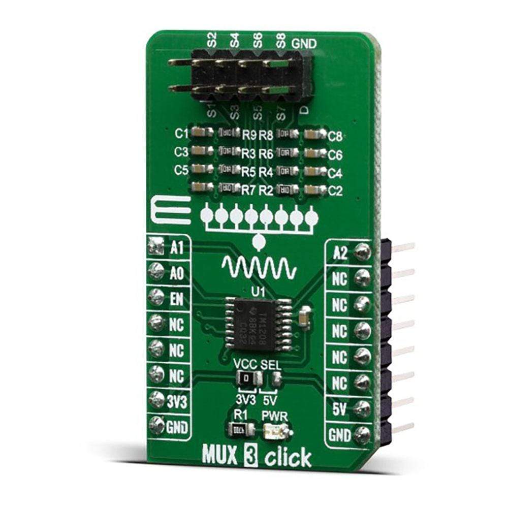
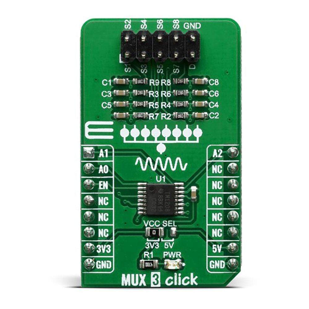
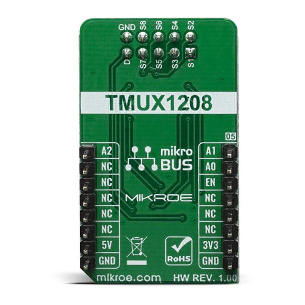
The MUX 3 Click Board™ is the general purpose multiplexer which offers multiplexing one input channel to eight single-ended output channels. Given the TMUX1208 wide operating supply options from 1.08 V to 5.5 V and support of bidirectional I/O signals, its allowing you use in a broad array of applications ranging from personal electronics to building automation applications such as: Heating, Smoke Detectors, Ventilation, Air Conditioning, Battery-Powered Equipment, Consumer Audio, etc.
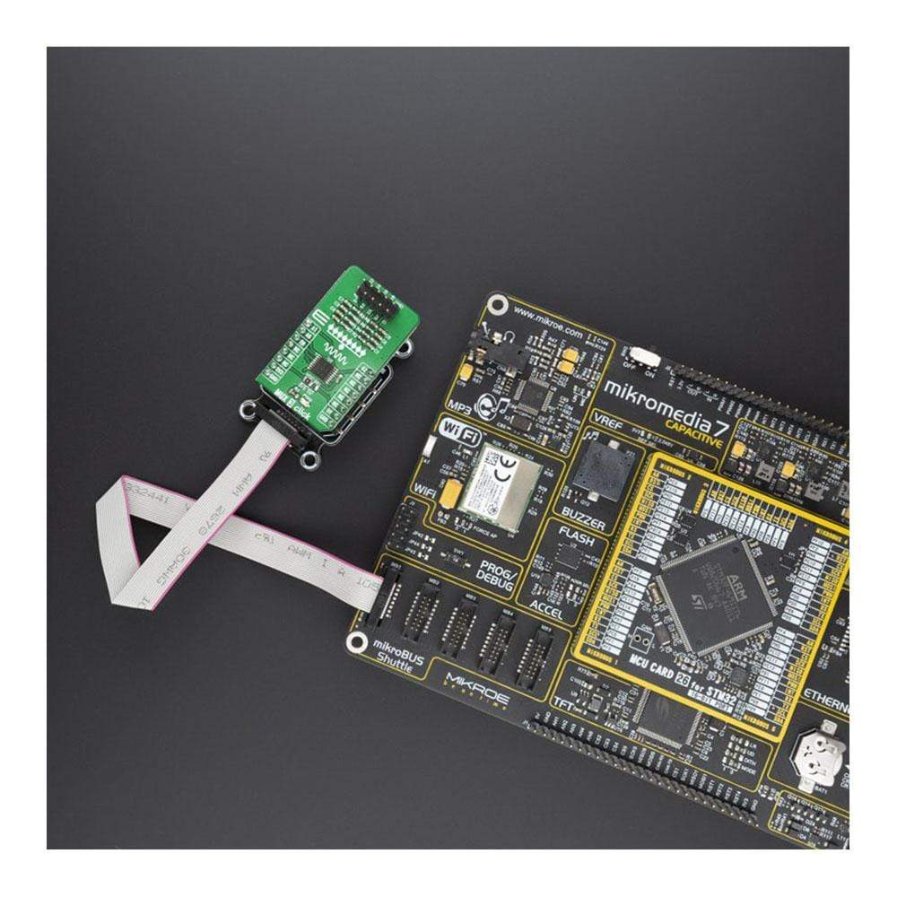
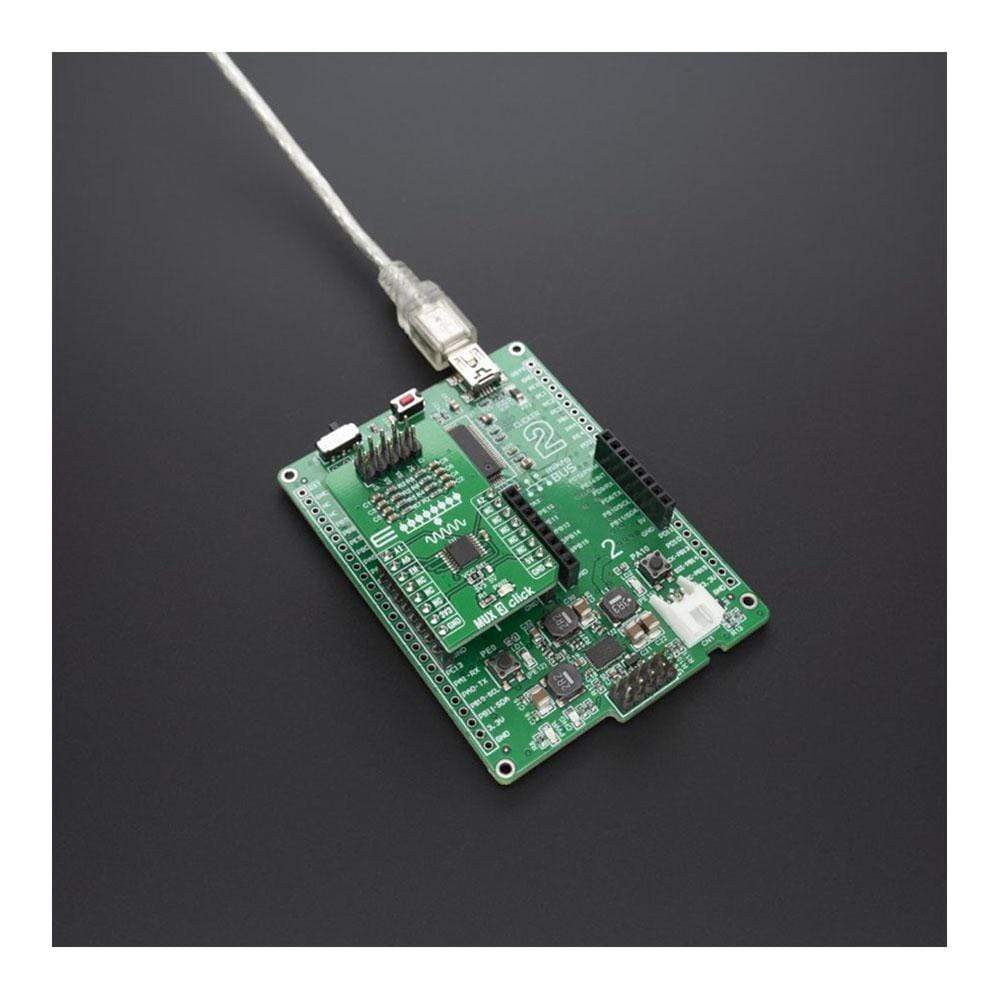
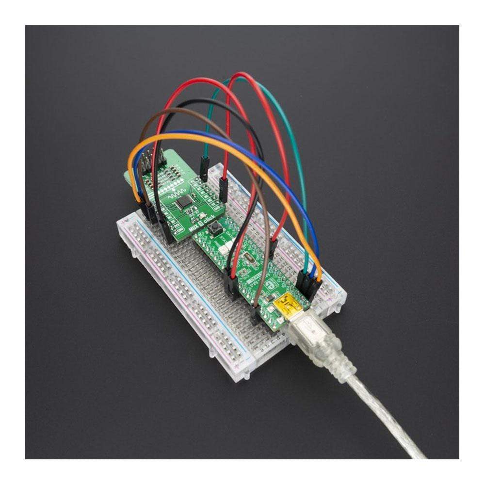
The MUX 3 Click Board™ is supported by a mikroSDK compliant library, which includes functions that simplify software development. This Click Board™ comes as a fully tested product, ready to be used on a system equipped with the mikroBUS™ socket.
Downloads
Le MUX 3 Click Board™ est un multiplexeur à usage général qui permet de multiplexer un canal d'entrée vers huit canaux de sortie asymétriques. Grâce aux nombreuses options d'alimentation de fonctionnement du TMUX1208 de 1,08 V à 5,5 V et à la prise en charge des signaux d'E/S bidirectionnels, il vous permet de l'utiliser dans un large éventail d'applications allant de l'électronique personnelle aux applications d'automatisation des bâtiments telles que : le chauffage, les détecteurs de fumée, la ventilation, la climatisation, les équipements alimentés par batterie, l'audio grand public, etc.
La carte Click Board™ MUX 3 est supportée par une bibliothèque compatible mikroSDK, qui comprend des fonctions qui simplifient le développement logiciel. Cette carte Click Board™ est un produit entièrement testé, prêt à être utilisé sur un système équipé du socket mikroBUS™.
| General Information | |
|---|---|
Part Number (SKU) |
MIKROE-3916
|
Manufacturer |
|
| Physical and Mechanical | |
Weight |
0.018 kg
|
| Other | |
EAN |
8606018719075
|
Frequently Asked Questions
Have a Question?
Be the first to ask a question about this.