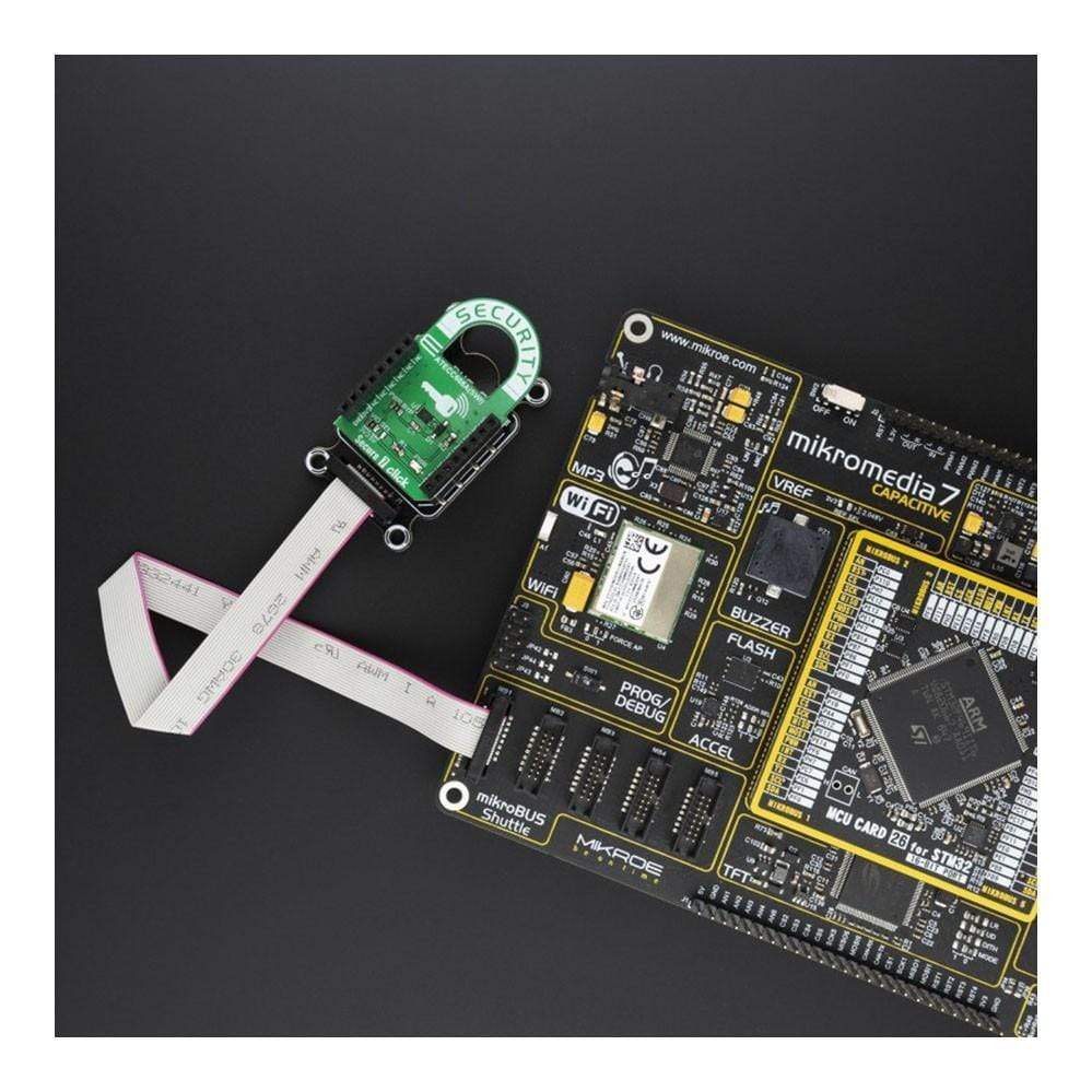
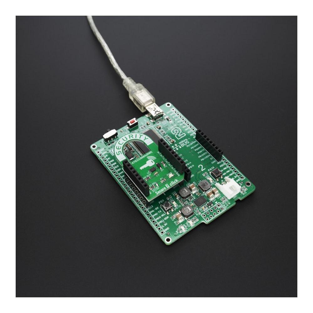
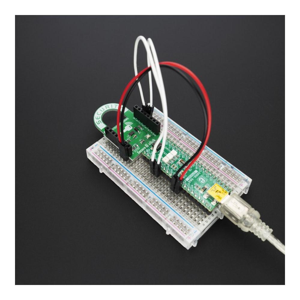
Tableau de bord sécurisé à 7 clics
Overview
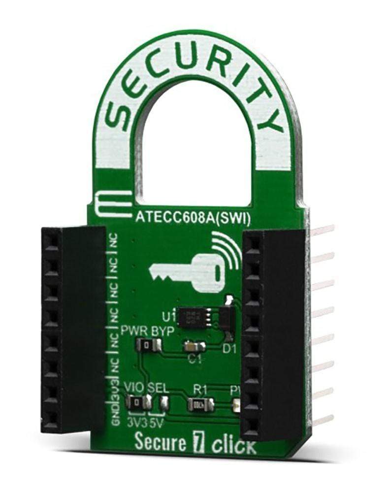
Le Secure 7 Click Board™ est équipé du coprocesseur cryptographique ATECC608A avec stockage de clés sécurisé basé sur le matériel, de Microchip. L'ATECC608A comprend une matrice EEPROM qui peut être utilisée pour stocker jusqu'à 16 clés, des certificats, diverses données en lecture/écriture, en lecture seule ou secrètes, la journalisation de la consommation et les configurations de sécurité. L'ATECC608A équipé sur ce Click Board™ prend en charge l'interface SWI avec un ensemble de commandes flexible, qui permet une utilisation dans diverses applications de sécurité, notamment la sécurité des points de terminaison des nœuds réseau/IoT, le démarrage sécurisé, le chiffrement des petits messages, la génération de clés pour le téléchargement de logiciels, le contrôle de l'écosystème, la lutte contre la contrefaçon et autres.
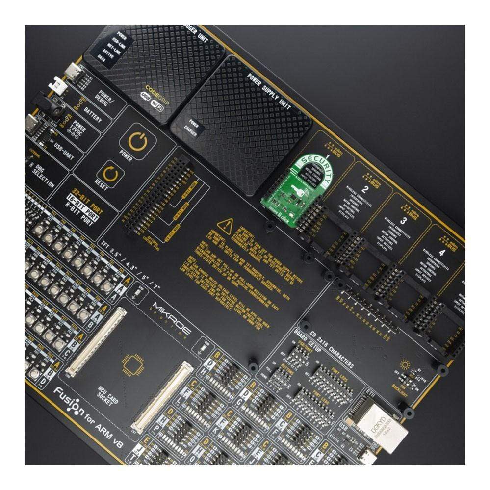
La carte Click Board™ Secure 7 est supportée par une bibliothèque compatible mikroSDK, qui comprend des fonctions qui simplifient le développement logiciel. Cette carte Click Board™ est un produit entièrement testé, prêt à être utilisé sur un système équipé du socket mikroBUS™.
How Does The Secure 7 Click Board™ Work?
The EEPROM array that is included in the ATECC608A coprocessor can be used for storage of up to 16 keys, certificates, miscellaneous read/write, read-only or secret data, consumption logging, and security configurations. Access to the various sections of memory can be restricted in a variety of ways and then the configuration can be locked to prevent changes. Therefore, the Secure 7 Click Board™ should mainly be used for security purposes.
Microchip's ATECC608A integrates ECDH (Elliptic Curve Diffie Hellman) security protocol, an ultra-secure method to provide a key agreement for encryption/decryption. It also integrates the ECDSA (Elliptic Curve Digital Signature Algorithm) sign-verify authentication for the Internet of Things (IoT) market, including home automation, industrial networking, accessory and consumable authentication, medical, mobile and more.
It features a wide array of defence mechanisms specifically designed to prevent physical attacks on the device itself, or logical attacks on the data transmitted between the device and the system. Hardware restrictions on the ways in which keys are used or generated provide further defence against certain styles of attack.
The ATECC608A has a flexible command set that allows use in many applications, including the Network/IoT Node Protection that authenticates node IDs, ensures the integrity of messages, and supports key agreement to create session keys for message encryption. It can also be used for Anti-Counterfeiting, meaning it validates that a removable, replaceable, or consumable client is authentic. Examples of clients could be system accessories, electronic daughter cards, or other spare parts. It can also be used to validate a software/firmware module or memory storage element. The next feature is Protecting Firmware or Media, which means it validates code stored in flash memory at boot to prevent unauthorized modifications, encrypt downloaded program files as a common broadcast, or uniquely encrypt code images to be usable on a single system only. Also, storing Secure Data, which means you can store secret keys for use by crypto accelerators in standard microprocessors. Programmable protection is available using encrypted/authenticated reads and writes. And finally, Checking User Password, and that ensures that it validates user-entered passwords without letting the expected value become known, maps memorable passwords to a random number, and securely exchanges password values with remote systems.
Access to the device is made through a standard SWI Interface at speeds of up to 1Mb/s, which can reduce the number of GPIOs required on the system processor, and/or reduce the number of pins on connectors. If the Single-Wire Interface is enabled, the remaining pin is available for use as a GPIO, an authenticated output or tamper input.
Each ATECC608A ships with a guaranteed unique 72-bit serial number. Using the cryptographic protocols supported by the device, a host system or remote server can verify a signature of the serial number to prove that the serial number is authentic and not a copy. Serial numbers are often stored in a standard Serial EEPROM; however, these can be easily copied with no way for the host to know if the serial number is authentic or if it is a clone.
The device is consuming very low current, especially while it is in sleep mode. The chip itself uses less than 150nA, in that case. The voltage range which can be used to power up the Secure 7 click, allows for it to work with both 3.3V and 5V capable MCUs. Therefore, this click board™ supports the parasitic power supply mode, where the main IC is powered via the communication line. When the onboard jumper PWR BYP is removed, Secure 7 click
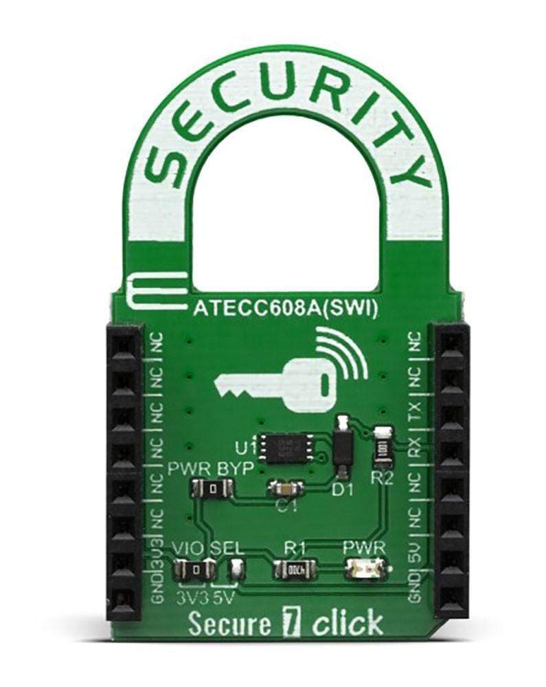
The chip itself uses a minimal number of pins; only the SWI lines are routed to the mikroBUS™ along with the 3.3V and 5V rails. The device can work with any of these voltages. It can be selected by soldering a small SMD jumper, labelled as VIO SEL to the correct position.
IMPORTANT: On the Secure 7 Click Board™, UART lines (RX and TX) are shorted and pulled high by the 1KΩ resistor. Basically, they act as a single line and only one trace is routed to the ATSHA204A IC. Further, it means that UART pins can be used only for SWI communication when this click board™ is used on a system.
Specifications
Type | Encryption |
Applications | IoT node security and ID, secure download and boot, ecosystem control, message security, anti-cloning, etc. |
On-board modules | ATECC608A cryptographic co-processor |
Key Features | Performs high-speed public key (PKI) algorithms, NIST Standard P256 elliptic curve support, SHA-256 hash algorithm with HMAC option, 256-bit key length, storage for up to 16 Keys |
Interface | SWI |
Compatibility | mikroBUS |
Click board size | M (42.9 x 25.4 mm) |
Input Voltage | 3.3V or 5V |
Pinout diagram
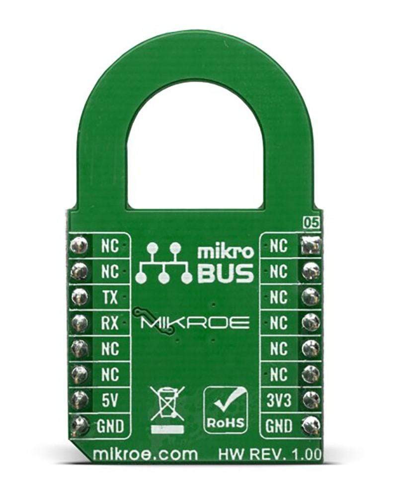
This table shows how the pinout of the Secure 7 Click Board™ corresponds to the pinout on the mikroBUS™ socket (the latter shown in the two middle columns).
Notes | Pin | Pin | Notes | ||||
---|---|---|---|---|---|---|---|
NC | 1 | AN | PWM | 16 | NC | ||
NC | 2 | RST | INT | 15 | NC | ||
NC | 3 | CS | RX | 14 | TX | SWI Line | |
NC | 4 | SCK | TX | 13 | RX | SWI Line | |
NC | 5 | MISO | SCL | 12 | NC | ||
NC | 6 | MOSI | SDA | 11 | NC | ||
Power Supply | 3.3V | 7 | 3.3V | 5V | 10 | 5V | Power supply |
Ground | GND | 8 | GND | GND | 9 | GND | Ground |
Onboard settings and indicators
Label | Name | Default | Description |
---|---|---|---|
LD1 | PWR LED | - | Power LED Indicator |
JP1 | VIO SEL | Left | Power supply voltage selection, left position 3V3, right position 5V |
Software Support
We provide a library for the Secure 7 Click Board™ on our LibStock page, as well as a demo application (example), developed using MikroElektronika compilers. The demo can run on all the main MikroElektronika development boards.
Library Description
The library covers all the necessary functions to control the Secure 7 Click Board™.
Key Functions
void secure7_send_bytes ( uint8_t count, uint8_t *p_buf )
- Send bytes function.void secure7_send_wake_token()
- Send wake token function.uint8_t secure7_receive_bytes ( uint8_t count, uint8_t *p_buf )
- Receive bytes function.
Example Description
The application is composed of three sections :
- System Initialization - Initializes GPIO and start to write log.
- Application Initialization - Initialization driver enables - GPIO and configure SWI for communication, also write log.
- Application Task - (code snippet) This is an example that demonstrates the use of the Secure 7 Click board. Data is read from the secure chip. If the readout is successful the data is then displayed on the serial port in hex format.
void application_task ( ) { if ( atcab_read_serial_number( &buffer_out[ 0 ] ) == ATCA_SUCCESS ) { mikrobus_logWrite( " Serial number : ", _LOG_LINE ); secure7_output_hex( &buffer_out[ 0 ], 9 ); } else { mikrobus_logWrite( " Reading serial number failed...", _LOG_LINE ); } mikrobus_logWrite( "----------------------------------------", _LOG_LINE ); Delay_ms ( 1000 ); if ( atcab_info( &buffer_out[ 0 ] ) == ATCA_SUCCESS ) { mikrobus_logWrite( " Device revision information : ", _LOG_LINE ); secure7_output_hex( &buffer_out[ 0 ], 4 ); } else { mikrobus_logWrite( " Reading device revision information failed...", _LOG_LINE ); } mikrobus_logWrite( "----------------------------------------", _LOG_LINE ); Delay_ms ( 1000 ); if ( atcab_read_config_zone( ATECC608A, &buffer_out[ 0 ] ) == ATCA_SUCCESS ) { mikrobus_logWrite( " First 32 bytes of device configuration :",_LOG_LINE ); secure7_output_hex( &buffer_out[ 0 ], 32 ); } else { mikrobus_logWrite( " Reading config zone failed...",_LOG_LINE ); } mikrobus_logWrite( "----------------------------------------", _LOG_LINE ); Delay_ms( 10000 ); }
Additional Functions :
secure7_set_output
- SWI directions set implementation - output.secure7_set_input
- SWI directions set implementation - input.secure7_output_hex
- Display output data in hex format.
The full application code, and ready to use projects can be found on our LibStock page.
Other mikroE Libraries used in the example:
- GPIO
- UART
- Conversions
Additional Notes and Information
Depending on the development board you are using, you may need a USB UART click, USB UART 2 click or RS232 click to connect to your PC, for development systems with no UART to USB interface available on the board. The terminal available in all MikroElektronika compilers, or any other terminal application of your choice, can be used to read the message.
mikroSDK
The Secure 7 Click Board™ is supported with mikroSDK - MikroElektronika Software Development Kit. To ensure proper operation of mikroSDK compliant Click board™ demo applications, mikroSDK should be downloaded from the LibStock and installed for the compiler you are using.
Frequently Asked Questions
Have a Question?
Be the first to ask a question about this.