


Mikroelektronika d.o.o.
Carte clic RS232 SPI
Carte clic RS232 SPI
SKU: MIKROE-3912
Impossible de charger la disponibilité du service de retrait


Overview
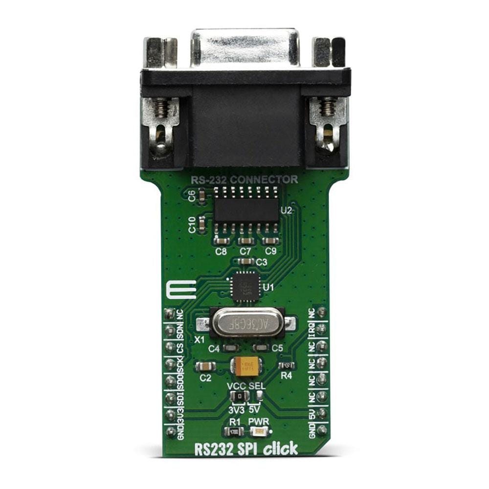
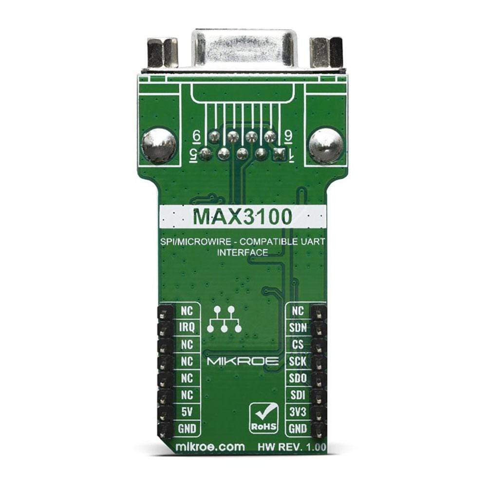
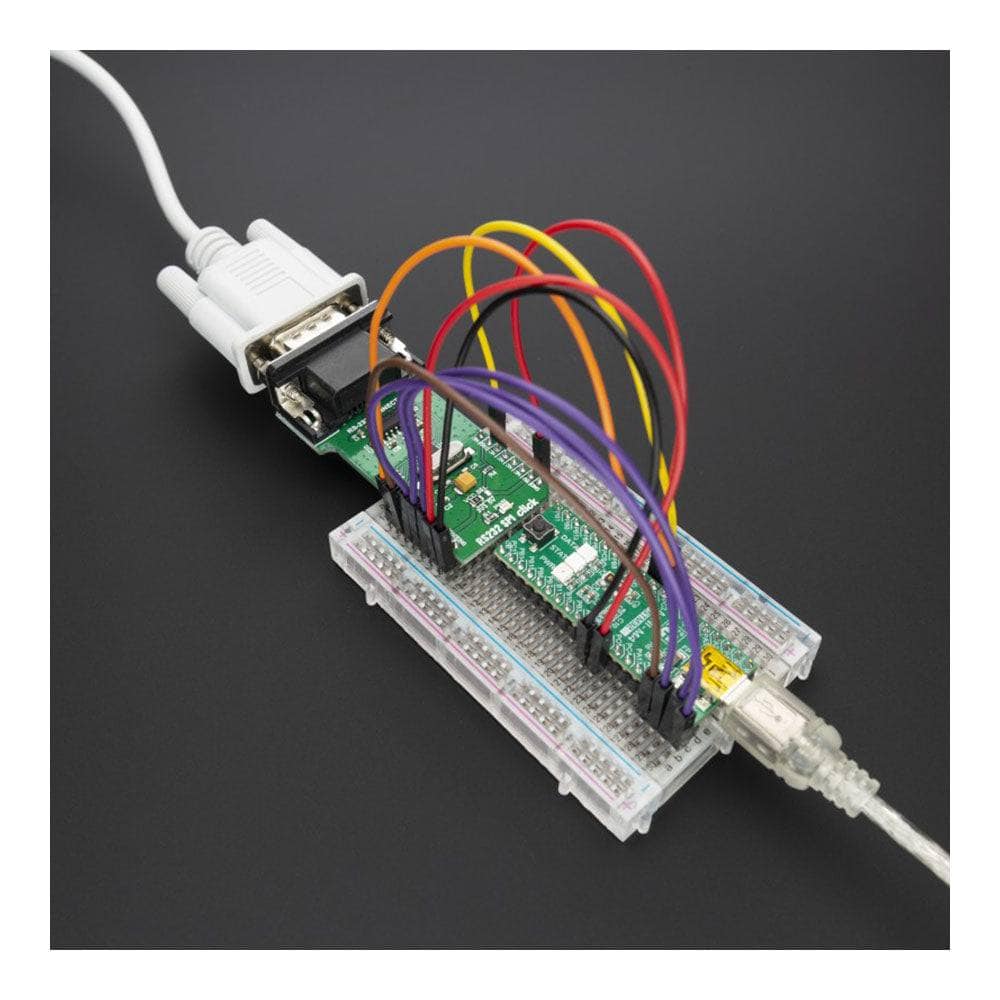
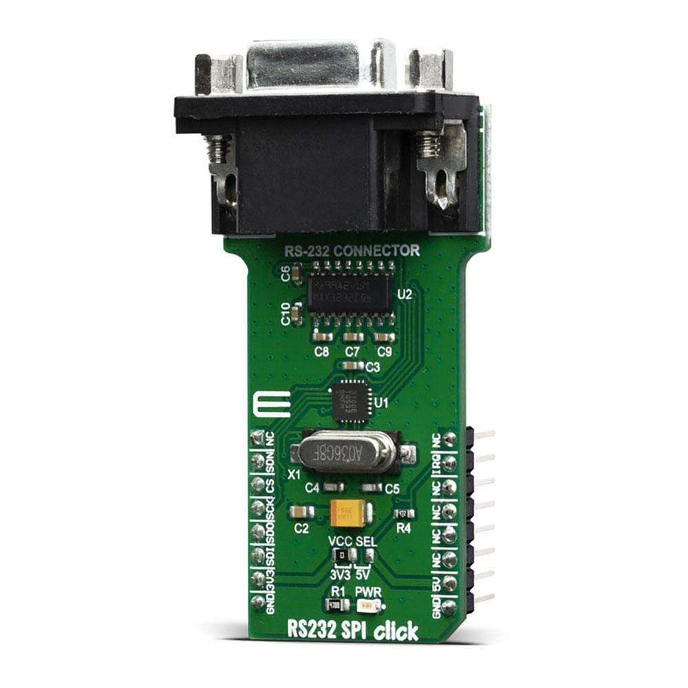
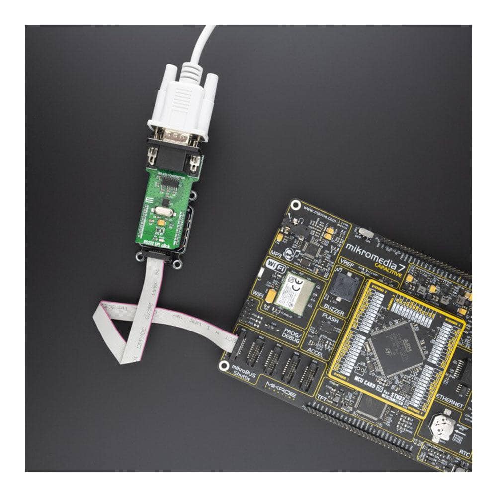
The RS232 SPI Click Board™ is based around the MAX3100, a universal asynchronous receiver transmitter (UART) - the first UART optimised explicitly for small microcontroller-based systems, from Maxim Integrated. Because of the features contained in its modules, the RS232 SPI Click Board™ can be used for handheld instruments, small networks in HVAC or Building control, UART in SPI systems, battery-powered systems, PDAs, notebooks and many more.
The RS232 SPI Click Board™ is supported by a mikroSDK compliant library, which includes functions that simplify software development. This Click Board™ comes as a thoroughly tested product, ready to be used on a system equipped with the mikroBUS™ socket.
Downloads
Le RS232 SPI Click Board™ est basé sur le MAX3100, un émetteur-récepteur asynchrone universel (UART) - le premier UART optimisé explicitement pour les petits systèmes basés sur des microcontrôleurs, de Maxim Integrated. En raison des fonctionnalités contenues dans ses modules, le RS232 SPI Click Board™ peut être utilisé pour les instruments portables, les petits réseaux de CVC ou de contrôle de bâtiment, l'UART dans les systèmes SPI, les systèmes alimentés par batterie, les PDA, les ordinateurs portables et bien d'autres.
La carte Click Board™ RS232 SPI est prise en charge par une bibliothèque compatible mikroSDK, qui comprend des fonctions qui simplifient le développement logiciel. Cette carte Click Board™ est un produit entièrement testé, prêt à être utilisé sur un système équipé de la prise mikroBUS™.
| General Information | |
|---|---|
Part Number (SKU) |
MIKROE-3912
|
Manufacturer |
|
| Physical and Mechanical | |
Weight |
0.029 kg
|
| Other | |
EAN |
8606018719112
|
Frequently Asked Questions
Have a Question?
Be the first to ask a question about this.