


Mikroelektronika d.o.o.
Planche à 4 clics H-Bridge
Planche à 4 clics H-Bridge
SKU: MIKROE-3787
Impossible de charger la disponibilité du service de retrait


Overview
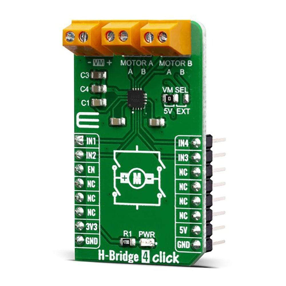
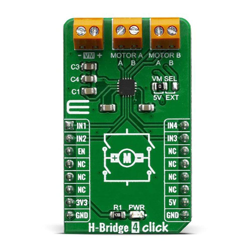
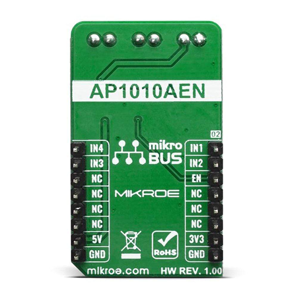
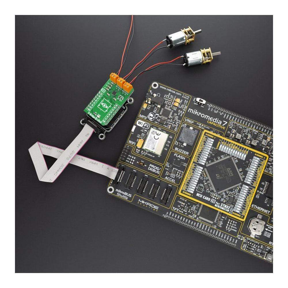
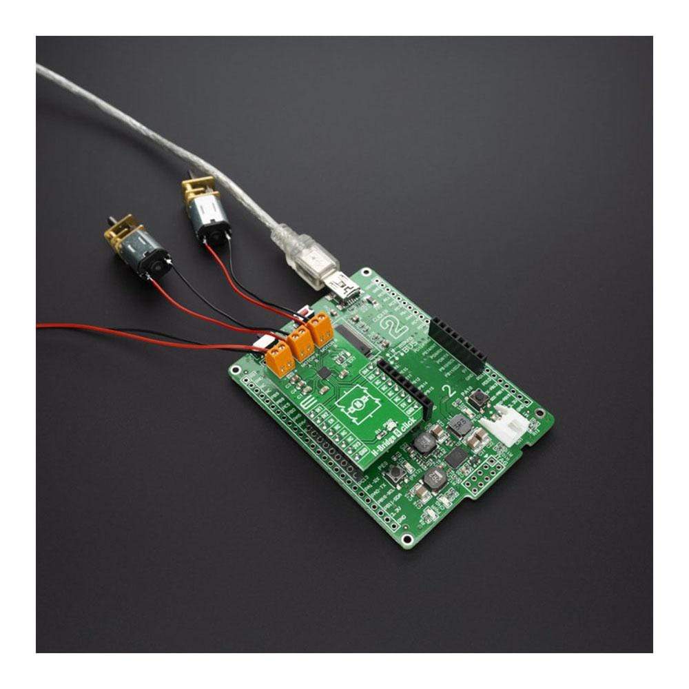
The H-Bridge 4 Click Board™ contains the AP1010AEN, which is a two-channel H-Bridge motor driver compatible with a motor operating voltage up to 18V and can drive two DC motors or one stepper motor. The protection circuit has an under-voltage lockout circuit, thermal shutdown circuit, and over-current protection circuit, and the over-current protection circuit can be disabled with the DIS OCP terminal.
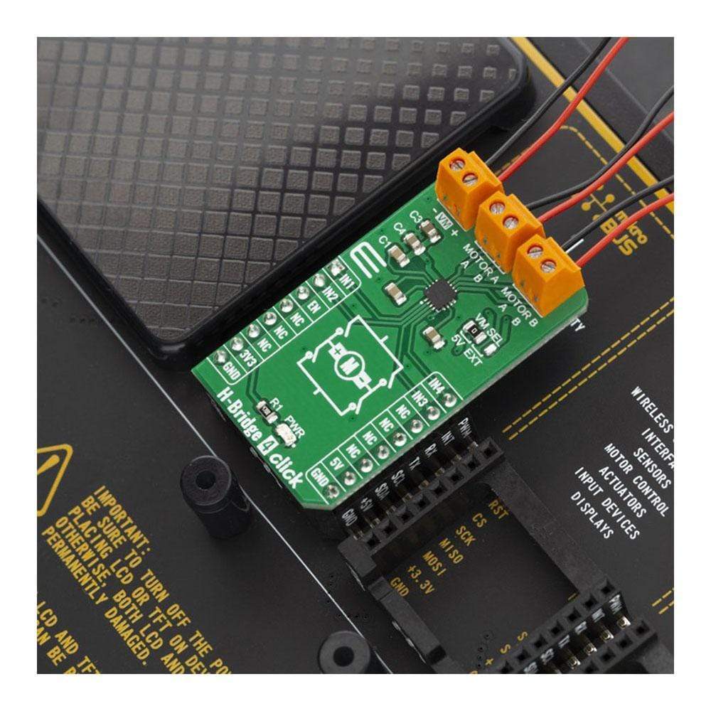
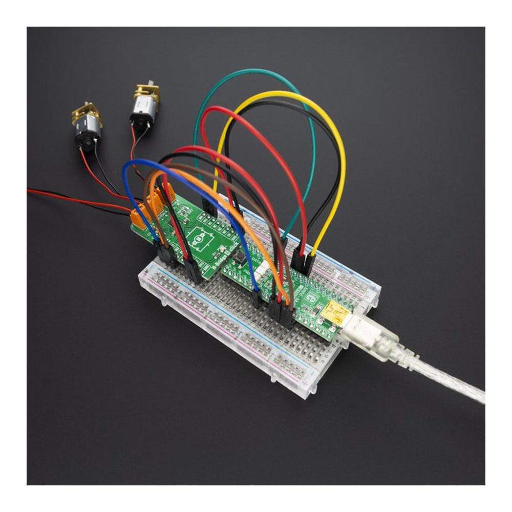
The H-Bridge 4 Click Board™ supports multiple connection options and can be used in different application setups which might include DC or Stepper motors.
Downloads
La carte H-Bridge 4 Click Board™ contient l'AP1010AEN, un pilote de moteur H-Bridge à deux canaux compatible avec une tension de fonctionnement du moteur jusqu'à 18 V et pouvant piloter deux moteurs à courant continu ou un moteur pas à pas. Le circuit de protection est doté d'un circuit de verrouillage de sous-tension, d'un circuit d'arrêt thermique et d'un circuit de protection contre les surintensités, et le circuit de protection contre les surintensités peut être désactivé avec le terminal DIS OCP.
Le H-Bridge 4 Click Board™ prend en charge plusieurs options de connexion et peut être utilisé dans différentes configurations d'application pouvant inclure des moteurs à courant continu ou pas à pas.
| General Information | |
|---|---|
Part Number (SKU) |
MIKROE-3787
|
Manufacturer |
|
| Physical and Mechanical | |
Weight |
0.019 kg
|
| Other | |
EAN |
8606018719891
|
Frequently Asked Questions
Have a Question?
Be the first to ask a question about this.