


Mikroelektronika d.o.o.
Tableau de clic Accel 13
Tableau de clic Accel 13
SKU: MIKROE-3742
Impossible de charger la disponibilité du service de retrait

Overview
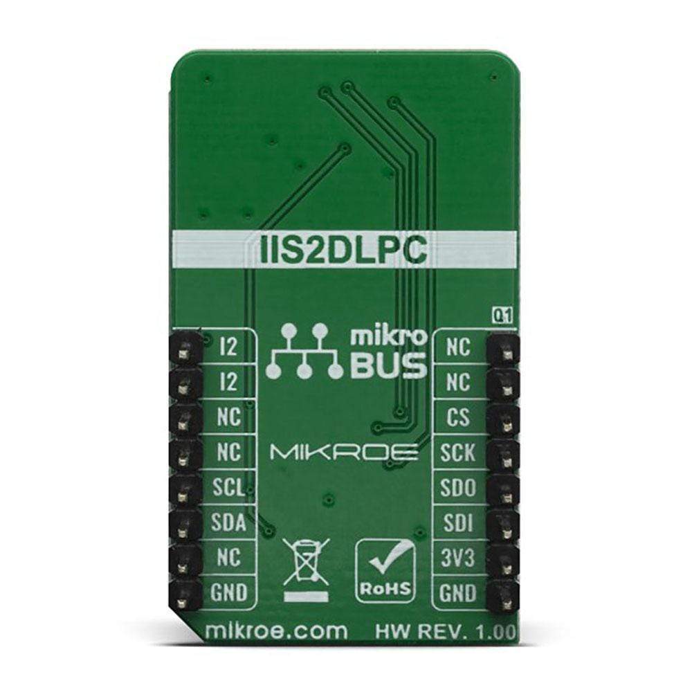
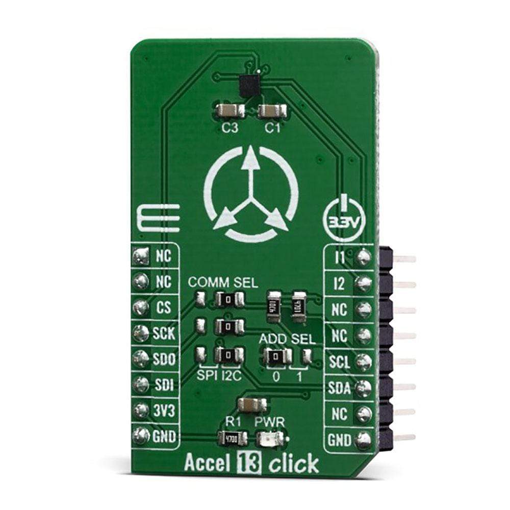
The Accel 13 Click Board™ features an ultra-low power triaxial accelerometer sensor with embedded intelligence, labelled as the IIS2DLPC. This Click Board™ allows linear motion and gravitational force measurements in ranges of ±2 g, ±4 g, ±8, and ±16 g in three perpendicular axes. This smart sensor allows the Accel 13 Click Board™ to detect many different events, including tap, double-tap, step counting, activity recognition (walk, run, stand still), activity change (any type of acceleration pattern change), orientation, and more. It features on-board data processing, offering the acceleration data directly, over the standard I2C or SPI interface.
Downloads
L' Accel 13 Click Board™ est doté d'un capteur accéléromètre triaxial à très faible consommation d'énergie avec intelligence intégrée, appelé IIS2DLPC. Ce Click Board™ permet des mesures de mouvement linéaire et de force gravitationnelle dans des plages de ±2 g, ±4 g, ±8 et ±16 g sur trois axes perpendiculaires. Ce capteur intelligent permet à l' Accel 13 Click Board™ de détecter de nombreux événements différents, notamment les appuis, les doubles appuis, le comptage des pas, la reconnaissance d'activité (marche, course, arrêt), le changement d'activité (tout type de changement de modèle d'accélération), l'orientation, etc. Il dispose d'un traitement de données intégré, offrant les données d'accélération directement, via l'interface standard I2C ou SPI.
| General Information | |
|---|---|
Part Number (SKU) |
MIKROE-3742
|
Manufacturer |
|
| Physical and Mechanical | |
Weight |
0.018 kg
|
| Other | |
EAN |
8606018716906
|
Frequently Asked Questions
Have a Question?
Be the first to ask a question about this.