Carte Click DeviceDrive
Key Features
- Batteries lithium-ion à deux cellules en série, courant de charge configurable jusqu'à 2 A, compatibles avec le contrôle hôte ou le mode autonome, gestion du chemin d'alimentation NVDC, circuit d'équilibrage de cellules intégré pour les cellules dépareillées, indicateurs d'état, interface I2C, NTC, et plus encore
- Basé sur le MP2672A - chargeur de batterie à découpage hautement intégré et flexible de Monolithic Power Systems (MPS)
- Peut être utilisé pour des applications portables, des machines de point de vente (POS), des applications générales à deux cellules, etc.
- mikroBUS : interface I2C
Overview
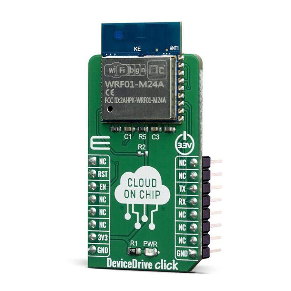
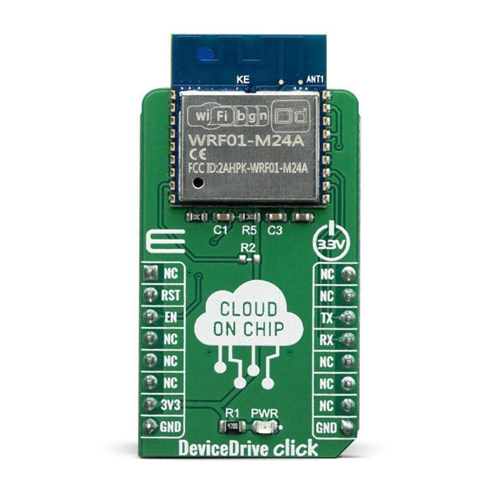
La carte DeviceDrive Click Board™ est une solution Cloud-on-Module complète avec fonctionnalité Wi-Fi et antenne PCB intégrée. Le module embarqué WRF01-M24A est livré préchargé avec le micrologiciel DeviceDrive qui décharge complètement la fonctionnalité de réseau Wi-Fi du processeur d'application et permet des fonctionnalités telles que la mise à niveau OTA, la connexion automatique au Cloud DeviceDrive et à l'application mobile. Chaque carte DeviceDrive Click Board™ est livrée avec l'activation GRATUITE pour le développement et le test complets de votre application.
Le module WRF01-M24A utilise l'interface UART (avec le format de commande JSON) pour la communication avec des périphériques externes. Avec cette carte, vous bénéficiez d'un accès GRATUIT à l'application mobile, au Cloud IoT-Hub et au micrologiciel WRF01 pour tester votre idée.
The board is based on a WiFi (802.11B/G/N) module from company Devicedrive with ready Firmware, which enables a plug & play Smart onboarding. In addition, you can use the Devicedrive Playground APP and Cloud for FREE for your application R&D. When your application is developed/tested, you can deal with Devicedrive to use your own Cloud or let Devicedrive help you to build your own Azure Cloud.
If you are interested to know how to start IoT development with the DeviceDrive Click Board™ and WRF01 Client Simulator, feel free to read our DeviceDrive Click Board™ User Manual.
The DeviceDrive click is a low-cost Cloud enabler device with extremely simple software integration, that will allow you an instant connection to the DeviceDrive Cloud. The WRF01-M24A module is equipped with low power MCU that runs the WiFi stack (not available for host-applications). The WRF01 provides unsurpassed ability to embed Wi-Fi capabilities into devices with the lowest cost, and minimal space requirement. The WRF01 has been designed for mobile electronics and Internet of Things (IoT) applications. The aim is to achieve the lowest power consumption possible with a combination of several proprietary techniques and very few components.
How Does The DeviceDrive Click Board™ Work?
The DeviceDrive Click Board™ is equipped with the WRF01-M24A a 802.11b/g/n module, specially programmed by the DeviceDrive company to enable direct connection to their Cloud. The module has integrated Tensilica Diamond L106 32bit cache-less microcontroller, which features extra low power consumption and like that is perfectly suited for the battery powered IoT applications.
The WRF01-M24A module handles all connectivity issues so that your device can simply send JSON on the UART and get reply from your selected cloud solution. The function of the WRF01-M24A is to work as a Wi-Fi adapter between your application and Cloud trough simple UART serial connectivity for commands and cloud transmissions. The WRF01 is a part of the DeviceDrive Smart Connectivity Platform (DDCP); a set of high performance, high integration wireless SOCs, designed for space and power constrained mobile platform designers.
In order to enable easies testing of the WRF01 module and Cloud solution, DeviceDrives offers also WRF01 Client Simulator. The program communicates with the WRF01 trough the serial ports and is suited for acting as a client and for prototyping IoT-Products.
For more information about DeviceDrive Cloud, WRF01 specifications and Client Simulator please visit their official page Downloads section.
The WRF01 comes with a LinkUp™ SDK for Android for easy Wi-Fi setup using HTTP/SSL. The LinkUp™ software takes care of all the complexity of connecting any device to your selected cloud system (SSID, password, token and product key), in the most safe and easy way.
Note, that you need to order a FREE product key from https:/manage.devicedrive.com to redirect the data to your selected cloud. The same product key should be applied to all devices of the same type communicating with the same target cloud. You can set the product key from the mobile app or through the serial interface.
DEVICEDRIVE Cloud
The DeviceDrive Cloud platform gives you the right tools and services to handle connections, gather and make sense of data, and provide the reliable customer experiences required for modern hardware devices. Your device sends JSON formatted data and gets JSON back from the cloud without having to worry about how it all happened. Their LinkUp SDKs lets your mobile App link the device seamlessly to the network, to the user and to the cloud.
Use their management portal to monitor and debug communication flow and direct the data to a destination of your choice for each of your products.
The DeviceDrive ecosystem consists of building blocks adjustable to the business model of each customer. It offers cloud services like OTA upgrades, Cloud Storage, Device Management, Data Analytics, VSaaS, Security and many others.
SPECIFICATIONS
Type | Cloud Routers,WiFi |
Applications | The WRF01 has been designed for mobile, wearable electronics and Internet of Things (IoT) applications. |
On-board modules | The WRF01-M24A module with 802.11 b/g/n protocol which handles all connectivity tasks and feature PCB antenna |
Key Features | Enable easy and fast connectivity to the cloud, low power mode, simple serial interface for communication. |
Interface | UART |
Compatibility | mikroBUS |
Click board size | M (42.9 x 25.4 mm) |
Input Voltage | 3.3V |
PINOUT DIAGRAM
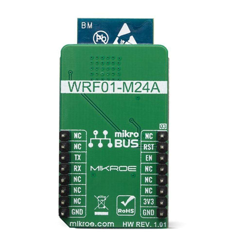
This table shows how the pinout of the DeviceDrive Click Board™ corresponds to the pinout on the mikroBUS™ socket (the latter shown in the two middle columns).
Notes | Pin | Pin | Notes | ||||
---|---|---|---|---|---|---|---|
NC | 1 | AN | PWM | 16 | NC | ||
Reset | RST | 2 | RST | INT | 15 | NC | |
Enable | EN | 3 | CS | RX | 14 | TX | UART Transmit |
NC | 4 | SCK | TX | 13 | RX | UART Receive | |
NC | 5 | MISO | SCL | 12 | NC | ||
NC | 6 | MOSI | SDA | 11 | NC | ||
Power Supply | 3.3V | 7 | 3.3V | 5V | 10 | NC | |
Ground | GND | 8 | GND | GND | 9 | GND | Ground |
ONBOARD SETTINGS AND INDICATORS
Label | Name | Default | Description |
---|---|---|---|
LD1 | PWR | - | Power LED Indicator |
Software Support
We provide a library for the DeviceDrive Click Board™ on our LibStock page, as well as a demo application (example), developed using MikroElektronika compilers. The demo can run on all the main MikroElektronika development boards.
Library Description
This library allows user to perform a control of the DeviceDrive Click Board™ and communication between device and cloud. User has options to send commands, configurations, messages, files... Every response from the WRF01 module will be sent to the user via handler function in JSON format. On this way every response on the sent command, every indication, connection status of the local network, device status can be checked and processed by the user. This library has also some necessary and important commands to perform network connection, module configuration and messages sending. For more details check full documentation.
Key Functions
void dd_uartDriverInit( T_DD_P gpioObj, T_DD_P uartObj )
- This function initializes UART serial interface.void dd_send_cmd( char *cmd_string )
- This function allows user to send a command to the module.T_DD_RETVAL dd_process( void )
- This function performs a response processing.void dd_setup( const char *param_code, const char *param_value )
- This command allows user to send setup commands to the WRF01.
Example Description
The application is composed of three sections :
- System Initialization - Initializes peripherals and pins.
- Application Initialization - Initializes UART serial interface and interrupt, executes wake up sequence and asks user which command will be performed for module setting. Also writes all possible commands to the uart terminal.
- Application Task - (code snippet) - Checks which character (command) was received from the user and executes the determined command. The response from the module will be received and processed independently on the user, did user send any of the possible commands or not. The response, module and connection status, debug and error reports, command messages will be sent to the UART terminal.
void applicationTask() { rx_cmd = UART_Rdy_Ptr(); if (rx_cmd != _DD_RSP_NOT_READY) { rx_cmd = UART_Rd_Ptr(); switch (rx_cmd) { case '1' : { mikrobus_logWrite( "> send message 1:", _LOG_LINE ); Delay_ms( 500 ); dd_send_cmd( &message_1[0] ); break; } case '2' : { mikrobus_logWrite( "> send message 2:", _LOG_LINE ); Delay_ms( 500 ); dd_send_cmd( &message_2[0] ); break; } case 't' : { mikrobus_logWrite( "> get time:", _LOG_LINE ); Delay_ms( 500 ); dd_get_time(); break; } case 'u' : { mikrobus_logWrite( "> check upgrade:", _LOG_LINE ); Delay_ms( 500 ); dd_check_upgrade(); break; } case 'f' : { mikrobus_logWrite( "> factory reset:", _LOG_LINE ); Delay_ms( 500 ); dd_factory_reset(); break; } case 'c' : { mikrobus_logWrite( "> connect to network:", _LOG_LINE ); Delay_ms( 500 ); dd_set_product_key( &product_key[0] ); processResponse( 1000 ); dd_connect( &network_name[0], &network_pwd[0] ); break; } case 'i' : { mikrobus_logWrite( "> introspect:", _LOG_LINE ); Delay_ms( 500 ); dd_send_cmd( &introspect_cmd[0] ); break; } case 'v' : { mikrobus_logWrite( "> turn on AP:", _LOG_LINE ); Delay_ms( 500 ); dd_show_device( &ap_on[0] ); break; } case 'l' : { mikrobus_logWrite( "> enable debug/error logging:", _LOG_LINE ); Delay_ms( 500 ); dd_setup( &debug_mode[0], &set_all[0] ); processResponse( 1000 ); dd_setup( &error_mode[0], &set_all[0] ); break; } case 's' : { mikrobus_logWrite( "> status:", _LOG_LINE ); Delay_ms( 500 ); dd_status(); break; } default : { mikrobus_logWrite( "> invalid command", _LOG_LINE ); Delay_ms( 500 ); logCmd(); break; } } } processResponse( 1 ); }
Additional Functions :
- getResponse - Gets and stores the response from the WRF01 module (handler function).
- processResponse - Checks the response in the determined time interval, and when response was ready writes response to the uart terminal.
- checkCmd - Allows user to enter the desired answer (command), y - yes, n - no.
- logCmd - Writes all possible commands for the user to the uart terminal.
- rx_isr - Catches the response bytes from the module one by one, when module was send some bytes to the host.
The full application code, and ready to use projects can be found on our LibStock page.
Other mikroE Libraries used in the example:
- UART
Depending on the development board you are using, you may need USB UART click, USB UART 2 click or RS232 click to connect to your PC, for development systems with no UART to USB interface available on the board. The terminal available in all MikroElektronika compilers, or any other terminal application of your choice, can be used to read the message.
MIKROSDK
The DeviceDrive Click Board™ is supported with mikroSDK - MikroElektronika Software Development Kit. To ensure proper operation of mikroSDK compliant Click board™ demo applications, mikroSDK should be downloaded from the LibStock and installed for the compiler you are using.
Frequently Asked Questions
Have a Question?
Be the first to ask a question about this.