


Mikroelektronika d.o.o.
Panneau de clic Light Temp
Panneau de clic Light Temp
SKU: MIKROE-3399
Impossible de charger la disponibilité du service de retrait


Overview
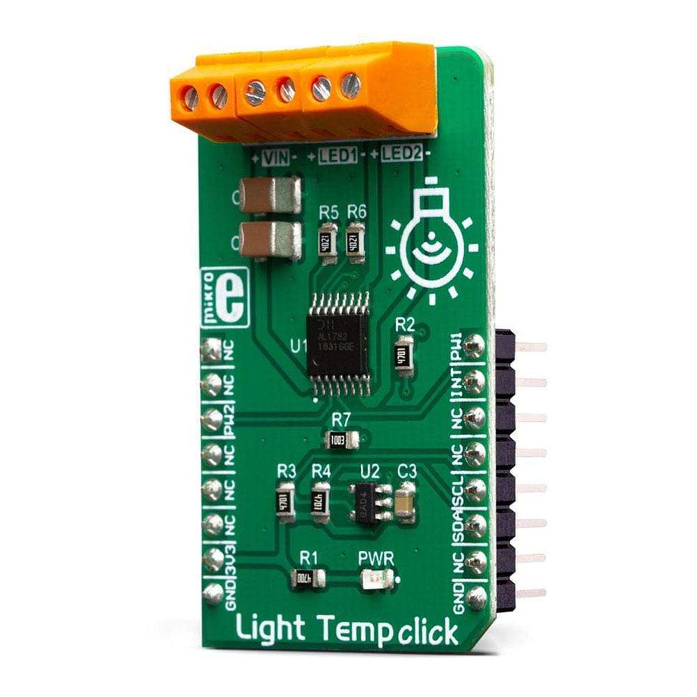
The Light Temp Click Board™ is a dual-channel LED driver, designed to be used in tunable Smart Connected Lighting (SCL) applications. It is based on the AL1782, a dual-channel PWM dimmable linear LED driver. By utilizing a high-frequency E-flicker free technology with Deep Dimming capability, it can be used in both single-channel dimmable white and dual-channel tunable white SCL applications.
The AL1782 IC features the Adaptive Thermal Management scheme, reducing power dissipation. It also integrates an abundance of protection features for increased reliability: under-voltage, open or short circuit at the output, and thermal protection.
Downloads
Le Light Temp Click Board™ est un pilote LED à deux canaux, conçu pour être utilisé dans les applications d'éclairage intelligent connecté (SCL) réglables. Il est basé sur l'AL1782, un pilote LED linéaire à intensité variable PWM à deux canaux. En utilisant une technologie sans scintillement électronique haute fréquence avec fonction de gradation profonde, il peut être utilisé à la fois dans les applications SCL à intensité variable à canal unique et à canal unique.
Le circuit intégré AL1782 est doté du système de gestion thermique adaptative, qui réduit la dissipation de puissance. Il intègre également de nombreuses fonctions de protection pour une fiabilité accrue : sous-tension, circuit ouvert ou court-circuit en sortie et protection thermique.
| General Information | |
|---|---|
Part Number (SKU) |
MIKROE-3399
|
Manufacturer |
|
| Physical and Mechanical | |
Weight |
0.02 kg
|
| Other | |
EAN |
8606018714704
|
Frequently Asked Questions
Have a Question?
Be the first to ask a question about this.