


Mikroelektronika d.o.o.
Tableau de clic ECG 3
Tableau de clic ECG 3
SKU: MIKROE-3273
Impossible de charger la disponibilité du service de retrait

Overview
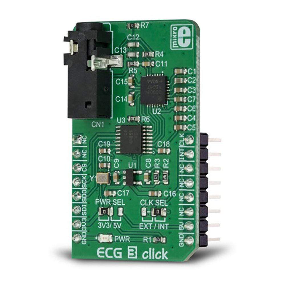
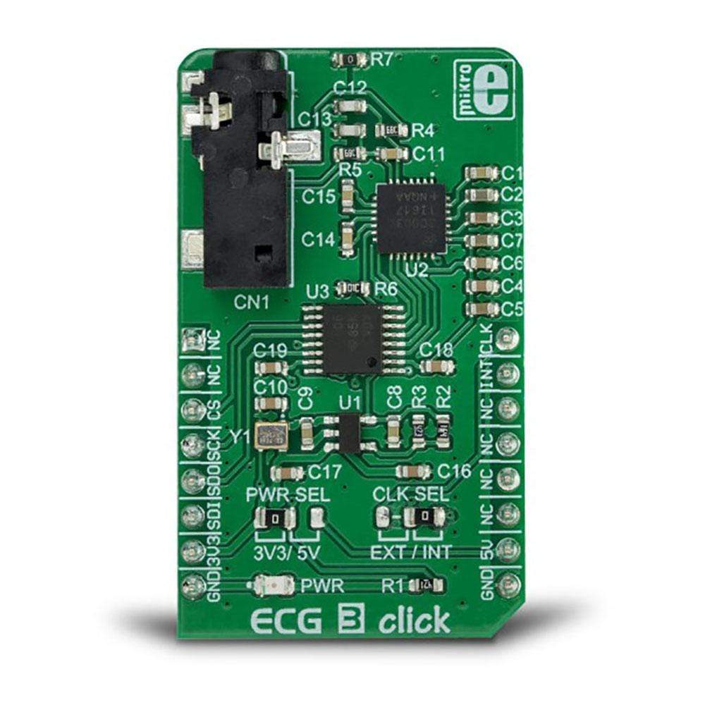
The ECG 3 Click Board™ is a complete solution for ECG and HR application development, utilizing a specialised IC with a clinical-grade analogue front-end (AFE). The Click Board™ uses the MAX30003 IC, an ultra-low-power, single-channel bio-sensor, which features a wide range of different options, making it an ideal solution for the development of heart rate and ECG monitoring applications, fitness applications, for the ECG bio-authentication, and similar applications related to heart monitoring.
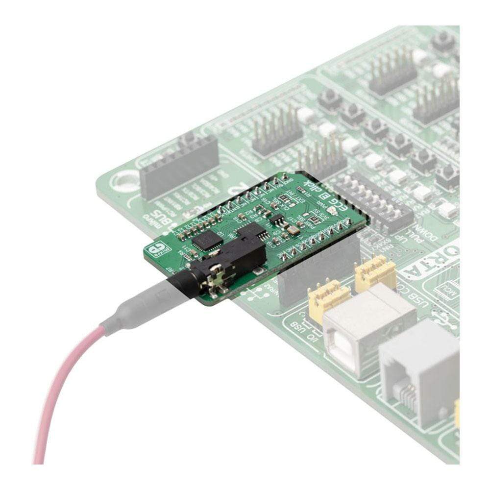
The ECG 3 Click Board™ is also equipped with a 3.5mm electrodes connector, making it ready to be used out of the box.
Downloads
L' ECG 3 Click Board ™ est une solution complète pour le développement d'applications ECG et HR, utilisant un circuit intégré spécialisé avec un frontal analogique de qualité clinique (AFE). Le Click Board™ utilise le circuit intégré MAX30003, un biocapteur monocanal à très faible consommation d'énergie, qui propose une large gamme d'options différentes, ce qui en fait une solution idéale pour le développement d'applications de surveillance de la fréquence cardiaque et de l'ECG, d'applications de fitness, pour la bio-authentification de l'ECG et d'applications similaires liées à la surveillance cardiaque.
L' ECG 3 Click Board™ est également équipé d'un connecteur d'électrodes de 3,5 mm, ce qui le rend prêt à être utilisé dès sa sortie de la boîte.
| General Information | |
|---|---|
Part Number (SKU) |
MIKROE-3273
|
Manufacturer |
|
| Physical and Mechanical | |
Weight |
0.019 kg
|
| Other | |
EAN |
8606018714018
|
Frequently Asked Questions
Have a Question?
Be the first to ask a question about this.