Cap Slider 2 Click Board
Overview
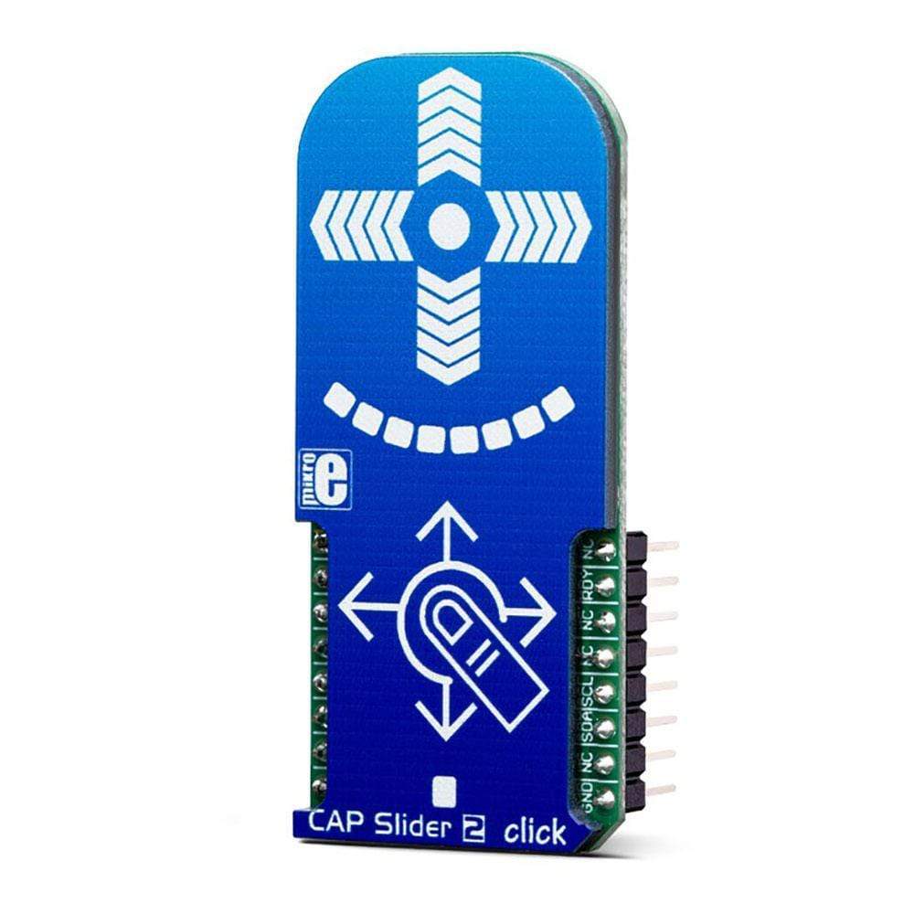
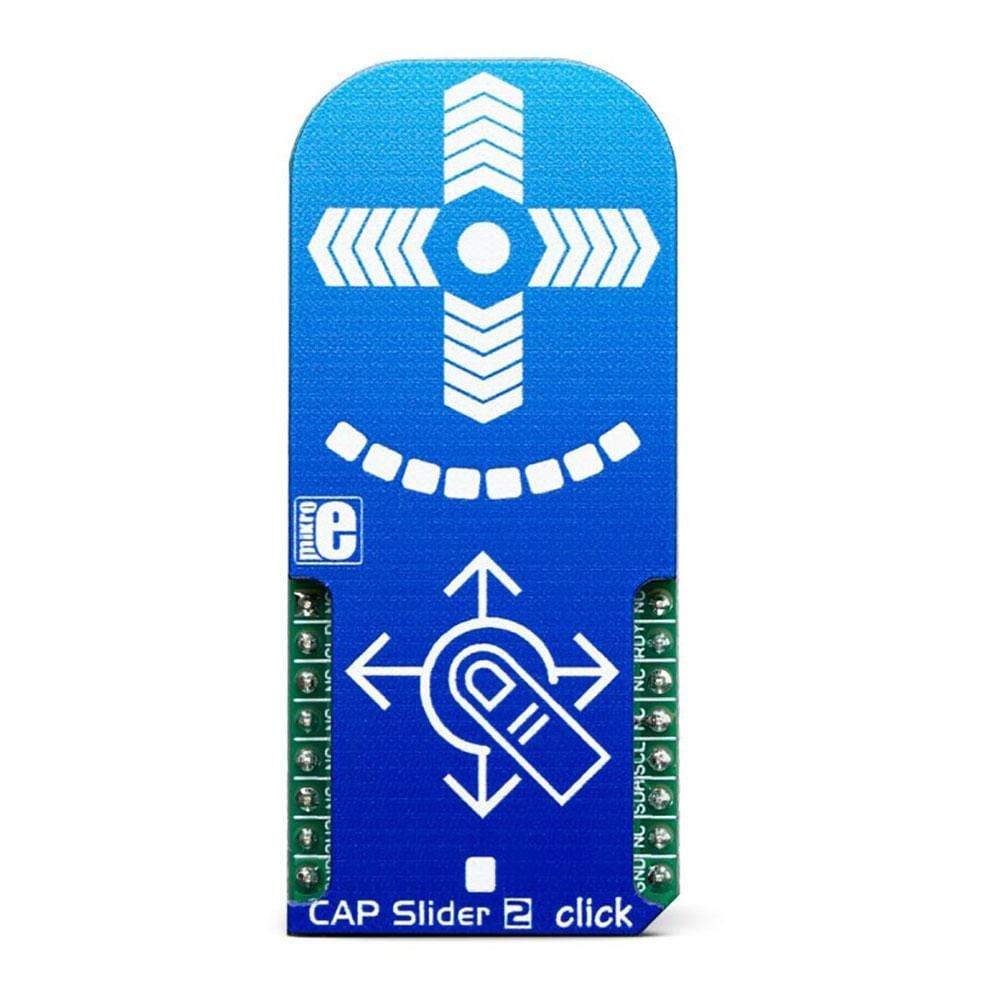
Le CAP Slider 2 Click Board™ est un capteur tactile capacitif avec des électrodes en forme de croix XY intégrées sur un Click Board™. Ce Click Board™ peut détecter le toucher même à travers du plastique, du bois ou d'autres matériaux diélectriques, qui peuvent être utilisés pour protéger la surface du PCB et la trace du pavé du capteur lui-même. Par conséquent, ce Click Board™ est livré avec un revêtement en plexiglas. Contrairement au bouton mécanique, le bouton tactile capacitif dure beaucoup plus longtemps, il n'est pas sujet aux dommages et à l'usure au fil du temps et il est très fiable.
Cette carte Click Board™ est dotée d'un capteur QS333 qui contient un module ProxSense® qui utilise une technologie brevetée pour fournir une détection des conditions de proximité et de contact sur de nombreuses lignes de détection.
Capacitive sensors are a very popular method of controlling various devices. Besides the aforementioned benefits, having a touch sensitive button on a device allows for a compact design, opens possibilities for various kinds of human-machine interface and - it looks good and modern, especially if 8 LEDs array that the CAP Slider 2 Click Board™ has onboard is taken into account. The CAP Slider 2 Click Board™ can find its place among many applications - for touch activated lighting controls, process control, touch activated control panels, toys and any other applications that need a switch or a joystick.
How Does The CAP Slider 2 Click Board™ Work?
Although it looks simple at first glance, capacitive touch sensing is not an easy task. There are many parameters that need to be sampled, filtered, compared and processed before positive touch detection and its position are confirmed. To make this possible, the CAP Slider 2 Click Board™ utilizes the IQS333, ProxSense® IC, a 9-channel projected (or 7-channel self) capacitive proximity and touch controller from Azoteq. This IC has some advanced features such as the auto drift compensation, Long proximity range, Automatic adjustment for optimal performance (ATI), two Configurable 11-bit sliders/scroll Slider 2s and more. These features enable CAP Slider 2 click exhibit very reliable and accurate touch detection.
Capacitive touch sensing is based on detecting a change in capacitance, due to the influence of a foreign object. Basically, the capacitance of the sensor, also known as the antenna, is measured and monitored and if a significant change occurs, after processing by the detection integrator, a touch event is acknowledged. To maximize performance, many routing requirements need to be met in the sensing electrodes design. The relation between the sensing elements in position and size is crucial. The CAP Slider 2 Click Board™ is designed with these requirements in mind and electrodes are „Projected XY-cross slider“ shaped.
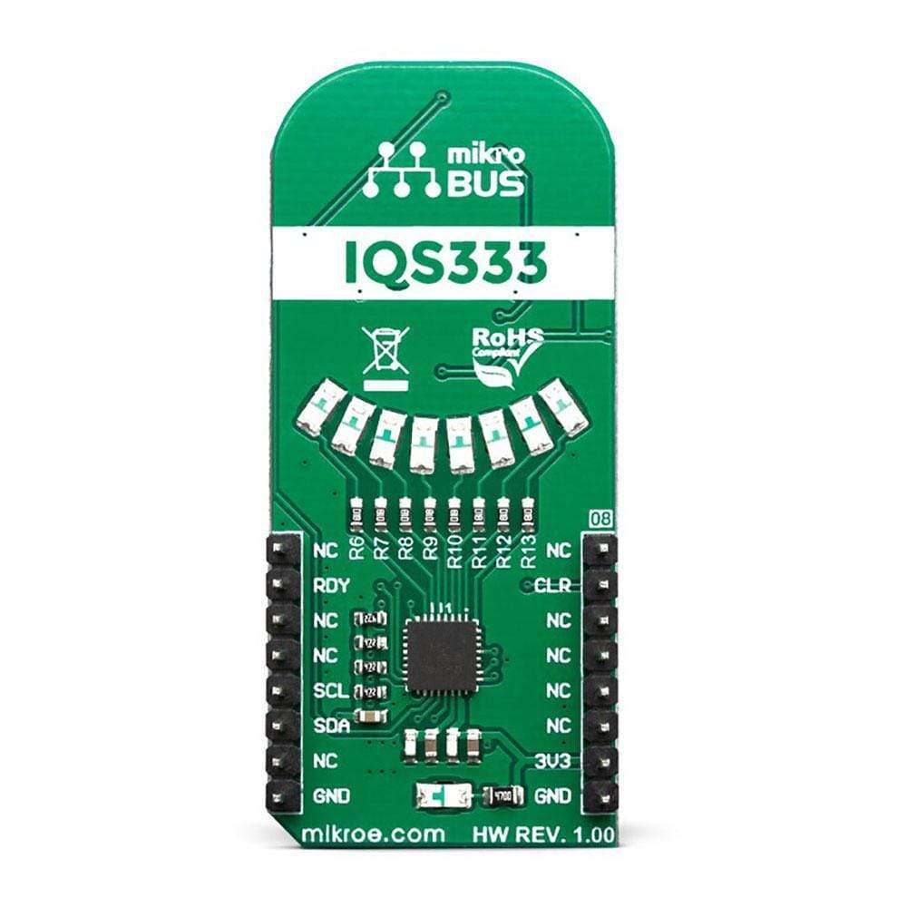
The CAP Slider 2 Click Board™ also contains 8 LEDs whose function can be user-defined. LEDs are connected to PWM LED driver pins on IQS333 which means that the user can turn LEDs on or off and control illumination, using the dimming modes that IQS333 supports.
The IQS333 IC interfaces to a master controller via a 3-wire (SDA, SCL, and RDY) serial interface bus that is I2C™ compatible, with a maximum communication speed of 400kbit/s. The host MCU has the capability to force a communication at any time, by pulling the RDY line low. The communication will start directly following the current conversion cycle. If the event is terminated by the watchdog timer, the device will reset.
After every power on cycle, the device will recalibrate itself. It will take some time, so it should be taken into consideration when building custom applications. MikroElektronika provides libraries and the demo application, that can be used as a reference for any future designs.
As mentioned before, the CAP Slider 2 Click Board™ is I2C™ compatible and uses SCL, SDA and RDY pins for communication which are routed to SCL, SDA and INT pin on mikroBUS™ respectively. Besides that, CLR pin is available on board which is routed to RST pin on mikroBUS™ and used to master reset the IC.
SPECIFICATIONS
Type | Capacitive |
Applications | The CAP Slider 2 Click Board™ can be used for touch activated lighting controls, process control, touch activated control panels, toys and any other applications that need a switch or an joystick. |
On-board modules | IQS333, ProxSense® IC, a 9-channel projected (or 7-channel self) capacitive proximity and touch controller from Azoteq. |
Key Features | Auto drift compensation, Long proximity range, Automatic adjustment for optimal performance (ATI), 2 Configurable 11-bit sliders/scroll wheels and more. |
Interface | GPIO,I2C |
Compatibility | mikroBUS |
Click board size | L (57.15 x 25.4 mm) |
Input Voltage | 3.3V |
PINOUT DIAGRAM
This table shows how the pinout of the CAP Slider 2 Click Board™ corresponds to the pinout on the mikroBUS™ socket (the latter shown in the two middle columns).
Notes | Pin | Pin | Notes | ||||
---|---|---|---|---|---|---|---|
NC | 1 | AN | PWM | 16 | NC | ||
Master Clear | CLR | 2 | RST | INT | 15 | RDY | Ready Output |
NC | 3 | CS | RX | 14 | NC | ||
NC | 4 | SCK | TX | 13 | NC | ||
NC | 5 | MISO | SCL | 12 | SCL | I2C Clock | |
NC | 6 | MOSI | SDA | 11 | SDA | I2C Data | |
Power Supply | 3.3V | 7 | 3.3V | 5V | 10 | NC | |
Ground | GND | 8 | GND | GND | 9 | GND | Ground |
ONBOARD SETTINGS AND INDICATORS
Label | Name | Default | Description |
---|---|---|---|
LD1-LD8 | - | - | User configurable LED indicator |
LD9 | PWR | - | Power LED Indicator |
Software Support
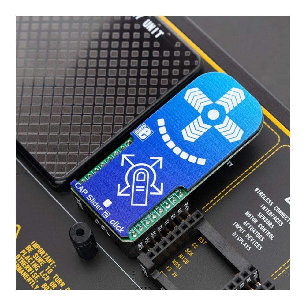
We provide a library for the CAP Slider 2 Click Board™ on our LibStock page, as well as a demo application (example), developed using MikroElektronika compilers. The demo can run on all the main MikroElektronika development boards.
Library Description
Key Functions
uint8_t capsldr2_writeReg( uint8_t register_address, uint8_t *dataIn, uint8_t nBytes )
- Function writes the determined number of bytes to the register.uint8_t capsldr2_readReg( uint8_t register_address, uint8_t *dataOut, uint8_t nBytes )
- Function reads the determined number of bytes from the register.void capsldr2_getData( uint16_t *wheelData1, uint16_t *wheelData2 )
- Function sets output LEDs depending on the input wheel data value on the way which is determined with ouputMode parameter.
Example Description
The application is composed of the three sections :
- System Initialization - Initializes peripherals and pins.
- Application Initialization - Initializes I2C interface, performs the device reset and configurations and sets the desired threshold value which determines sensor sensitivity. Note : User should wait for a 4 seconds about to device be stabilized.
- Application Task - (code snippet) - Reads sense values from capacitance cross (both wheels) when data was ready for reading, converts these values to 8 step resolution and selects on which way the LEDs be activated, depending in the which way finger (object) is pulled over the cross sensor. Results will be sent to the uart terminal.
void applicationTask() { readyCheck = capsldr2_checkDataReady(); if (readyCheck == _CAPSLDR2_DATA_READY) { capsldr2_getData( &dataWheel1, &dataWheel2 ); wheelAvrg1 += dataWheel1; wheelAvrg2 += dataWheel2; cnt++; } if (cnt == 1) { if ((wheelAvrg2 / cnt) > 1800) { horizontalCheck(); capsldr2_setOutput( outVal, outMode ); } else if (((wheelAvrg2 / cnt) < 1650) && ((wheelAvrg2 / cnt) > 1000)) { verticalCheck(); capsldr2_setOutput( outVal, outMode ); } wheelAvrg1 = 0; wheelAvrg2 = 0; cnt = 0; } }
Additional Functions :
- horizontalCheck - Checks is finger pulled over the cross to the left or right side.
- verticalCheck - Checks is finger pulled over the cross to up or to down.
Other mikroE Libraries used in the example:
I2C
Additional Notes and Information
Depending on the development board you are using, you may need a USB UART click, USB UART 2 click or RS232 click to connect to your PC, for development systems with no UART to USB interface available on the board. The terminal available in all MikroElektronika compilers, or any other terminal application of your choice, can be used to read the message.
MIKROSDK
The CAP Slider 2 Click Board™ is supported with mikroSDK - MikroElektronika Software Development Kit. To ensure proper operation of mikroSDK compliant click board demo applications, mikroSDK should be downloaded from the LibStock and installed for the compiler you are using.
Frequently Asked Questions
Have a Question?
Be the first to ask a question about this.