


Mikroelektronika d.o.o.
Carte à clic PWR Meter 2
Carte à clic PWR Meter 2
SKU: MIKROE-3150
Impossible de charger la disponibilité du service de retrait
Overview
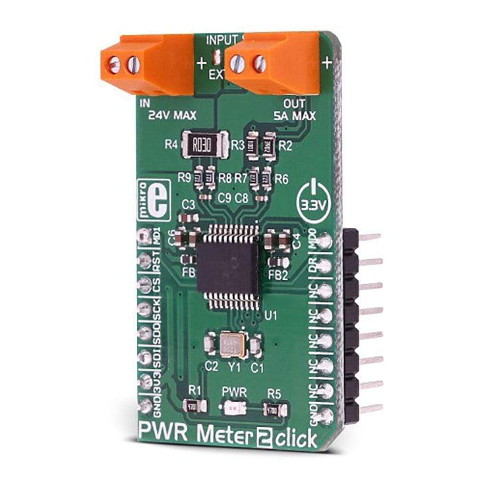
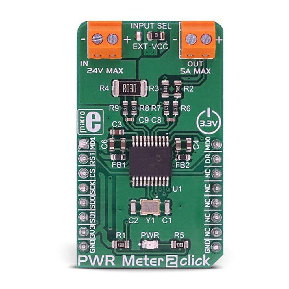
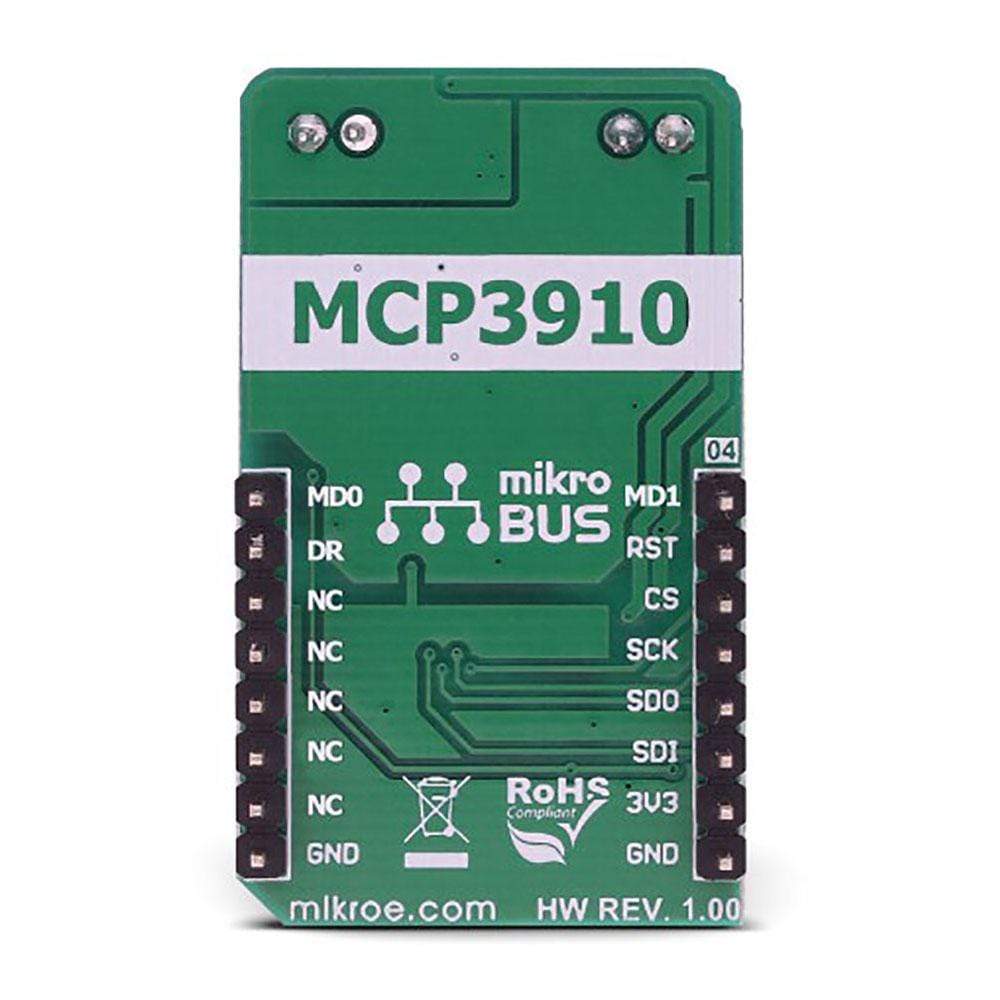
The PWR Meter 2 Click Board™ is a compact and accurate power monitoring Click Board™, capable of measuring and monitoring voltage up to 24V and current up to 5A. It carries the MCP3910, an integrated Analog Front End (AFE) device, which consists of two delta-sigma A/D Converters (ADC), two Programmable Gain Amplifiers (PGA), phase delay compensation section, voltage reference section, digital offset and gain error calibration registers, and industry-standard SPI interface. This device allows to build power monitoring device with a reasonably low count of elements: A current sensing resistor connected to one channel with the voltage divider connected to the second channel is all that it is required to perform an accurate power measurement.
Downloads
Le PWR Meter 2 Click Board™ est un Click Board™ de surveillance de puissance compact et précis, capable de mesurer et de surveiller une tension jusqu'à 24 V et un courant jusqu'à 5 A. Il est équipé du MCP3910, un dispositif frontal analogique intégré (AFE), qui se compose de deux convertisseurs A/N delta-sigma (ADC), de deux amplificateurs à gain programmable (PGA), d'une section de compensation de retard de phase, d'une section de référence de tension, de registres d'étalonnage d'erreur de décalage et de gain numériques et d'une interface SPI standard de l'industrie. Ce dispositif permet de construire un dispositif de surveillance de puissance avec un nombre raisonnablement faible d'éléments : une résistance de détection de courant connectée à un canal avec le diviseur de tension connecté au deuxième canal est tout ce qu'il faut pour effectuer une mesure de puissance précise.
| General Information | |
|---|---|
Part Number (SKU) |
MIKROE-3150
|
Manufacturer |
|
| Physical and Mechanical | |
Weight |
0.03 kg
|
| Other | |
EAN |
8606018713530
|
Frequently Asked Questions
Have a Question?
Be the first to ask a question about this.