Carte de clic servo
Carte de clic servo
Overview
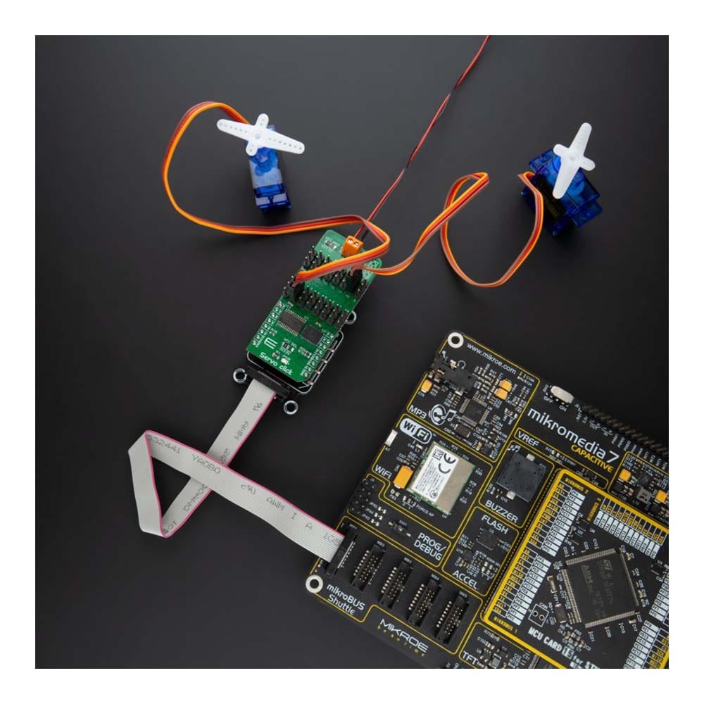
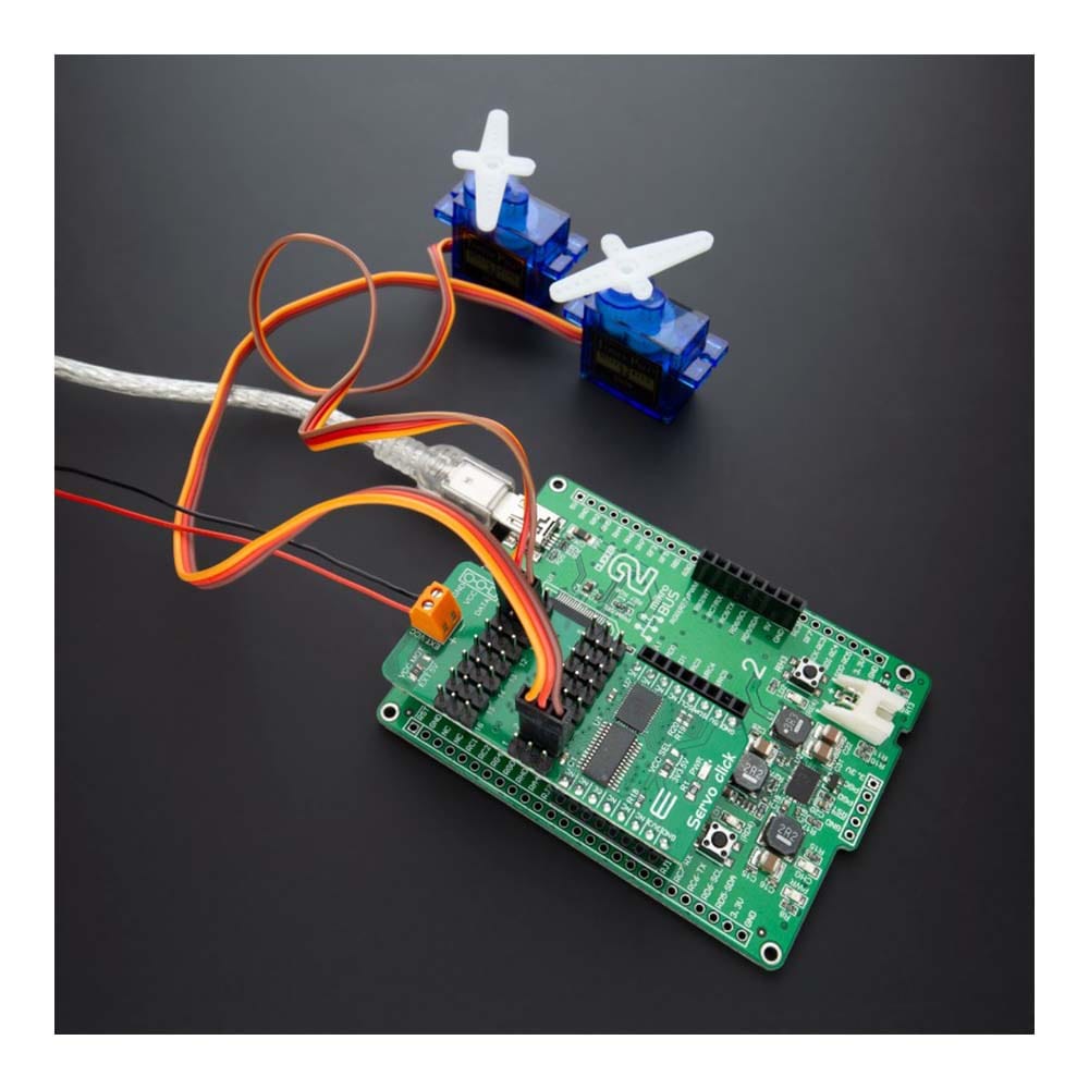
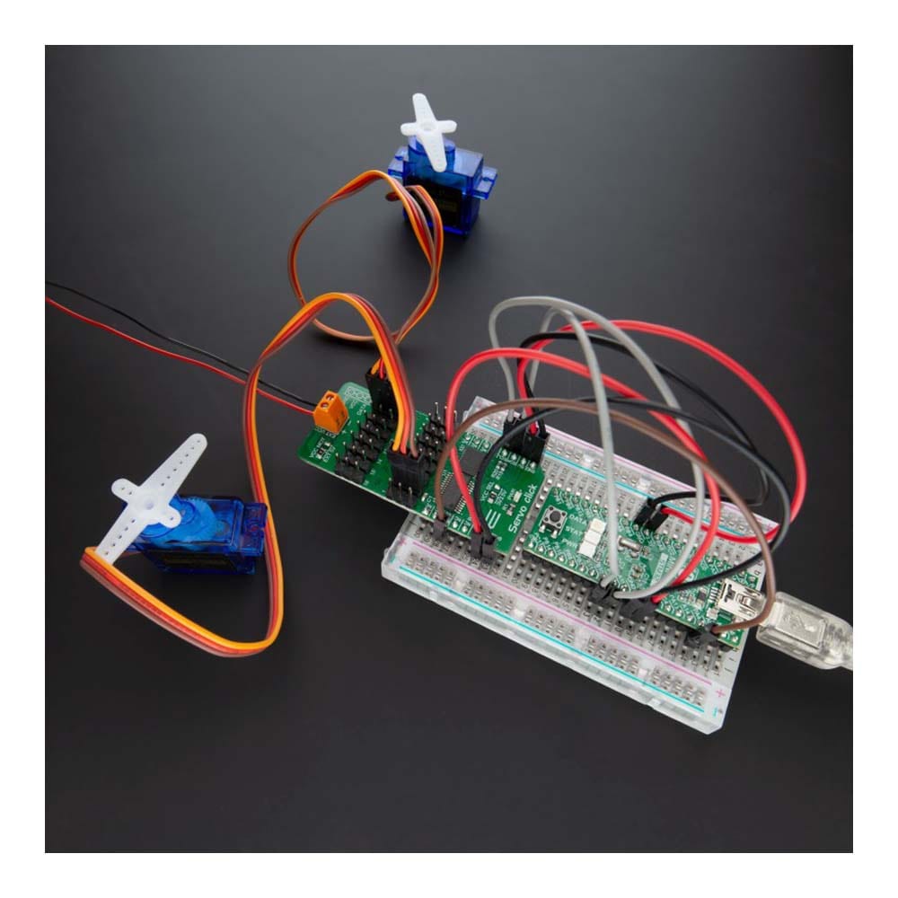
Présentation du Servo Click Board™ : révolutionnez votre servocommande
Vous en avez assez de vous débattre avec des options de contrôle de servo limitées ? Ne cherchez plus ! Le Servo Click Board™ est là pour transformer votre expérience de contrôle de servo.
Libérez la puissance du contrôle PWM à 16 canaux
Dites adieu aux limitations d'un seul canal. Avec le Servo Click Board™, vous pouvez contrôler simultanément 16 servomoteurs ! Chaque servomoteur bénéficie de son propre signal PWM programmable, vous offrant une flexibilité et une précision inégalées dans vos projets.
Ajustez les performances de votre servo
La précision est importante. C'est pourquoi nous avons équipé le Servo Click Board™ d'une plage de fréquences de signal PWM programmable de 24 Hz à 1526 Hz. Cette plage est soigneusement choisie pour s'adapter à différents types de servomoteurs, garantissant que vos créations se déplacent avec la plus grande précision et exactitude.
Informations en temps réel grâce à la détection de tension
Ce qui distingue le Servo Click Board™, c'est son convertisseur A/N 16 bits, qui échantillonne la chute de tension sur la résistance shunt de chaque canal. Cela signifie que vous obtenez un retour d'information en temps réel sur la consommation de courant du servo, ce qui vous permet d'optimiser les performances et d'éviter la surchauffe sans avoir à modifier vos servos.
Pourquoi choisir le Servo Click Board™ ?
- Contrôle sans effort : contrôlez jusqu'à 16 servos en toute simplicité, rationalisez vos projets et gagnez du temps.
- Précision à chaque mouvement : réglez vos servos à la perfection avec une large plage de fréquences de signal PWM.
- Protégez vos servos : surveillez la consommation de courant en temps réel pour éviter les dommages et améliorer la longévité.
Faites le bon choix et découvrez un nouveau niveau de contrôle des servomoteurs avec le Servo Click Board™. Améliorez vos projets, débloquez des possibilités illimitées et rejoignez les rangs des clients satisfaits qui ont déjà fait le changement.
Prêt à révolutionner votre servocommande ? Cliquez sur le bouton ci-dessous et faites le premier pas vers un avenir plus brillant et plus précis !
Obtenez votre Servo Click Board™ maintenant
Ne manquez pas cette innovation révolutionnaire. Mettez à niveau votre servocommande dès aujourd'hui !
How Does The Servo Click Board™ Work?
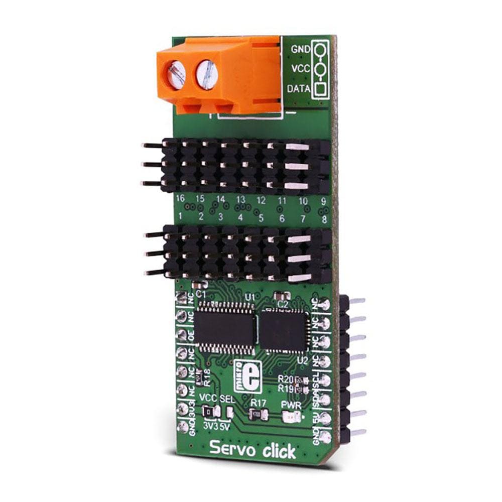
The Servo Click Board™ is based on the PCA9685, an integrated 12-bit 16-channel PWM driver which can be configured to either sink 25mA per channel or drive each channel sourcing up to 10mA from NXP. Each channel has its duty cycle independently set from 0% to 100%. Offering 16 independent channels, each with its own PWM duty cycle and current sensing ability, this Click board™ represents a powerful servo controller, especially useful when a large number of servos needs to be controlled simply and easily. The frequency of the control PWM signal can be programmed in the range from 24 Hz to 1526 Hz.
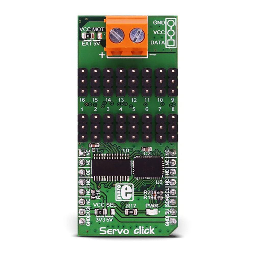
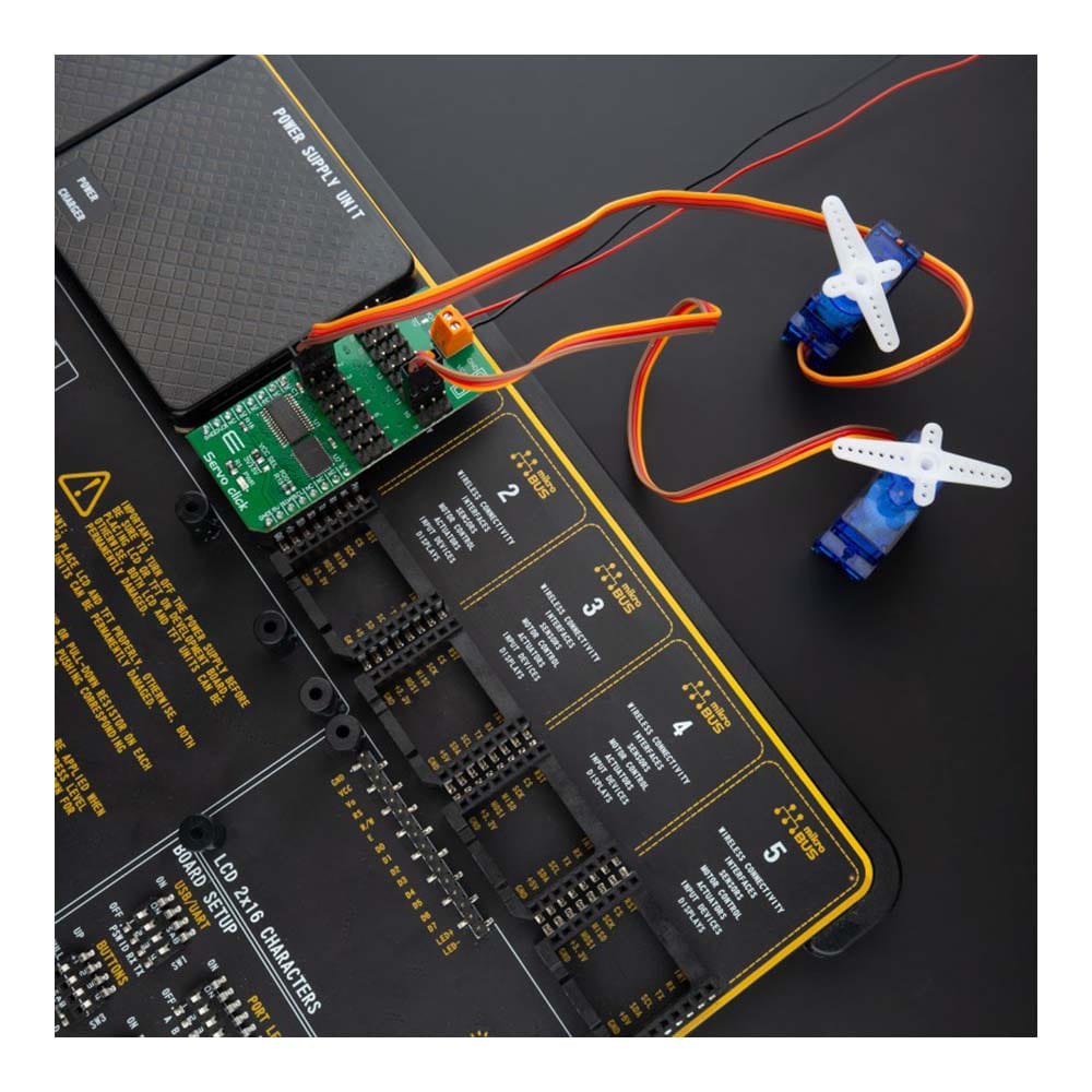
The servo can be connected to any of the sixteen headers located on the Servo Click Board™. The output signal frequency is determined by the Prescaler value, which is written to the appropriate register. The output channels can be set either in the open-drain or in the push-pull configuration. In the first case, they will be able to sink up to 25mA from up to 5V power supply, while in the second case, they will be able to both drive with up to 10mA or sink up to 25mA.
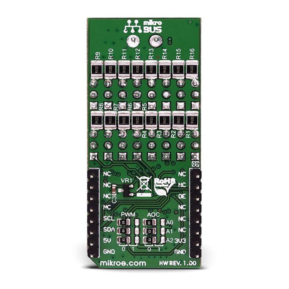
The Servo Click Board™ also has an accurate 16bit A/D converter the LTC2497 from Analog Devices used to sample the voltage drop across the shunt resistor on each of the 16 channels giving feedback on the servo current consumption. The ADC uses an accurate reference of 2.048V provided by an onboard reference voltage regulator MAX6106 from Maxim Integrated. An extremely low noise of this ADC coupled with a low reference voltage allows small voltage drops across the shunt resistor to be accurately converted.
The Servo Click Board™ communicates with MCU using the standard I2C 2-Wire interface with a frequency up to 100kHz in the Standard, up to 400 kHz in the Fast, and up to 1MHz in the Fast-Plus mode. There are two more SMD jumpers, labelled as the PWM and ADC, located at the bottom of the Click board™ that allows selection of the slave I2C address for each of the two onboard ICs. It also has an external connector that can provide more power for servos that operate with heavier loads. That's why the SMD jumper labelled as VCC MOT should be at the EXT position. In this case, an external PSU that can provide more current can be used.
The PCA9685 also offers Output Enable pin, routed to the mikroBUS™ CS pin, labelled as the OE. A LOW logic level on this pin will set all the outputs to the predefined logic state, turning the PWM generators OFF. This may either leave the servo into the fixed position or turn it down completely, depending on the servo model.
The Servo Click Board™ is designed to be operated with both 3.3V and 5V logic voltage levels that can be selected via VCC SEL jumper. This allows for both 3.3V and 5V capable MCUs to use the I2C communication lines properly.
SPECIFICATIONS
Type | Servo |
Applications | The Servo Click Board™ can be used in applications when a large number of servos needs to be easily controlled in the movie or theater industry (animatronics), robotics, RC toys, and similar. |
On-board modules | The Servo Click Board™ is based on the PCA9685, an integrated 12-bit 16-channel PWM driver which can be configured to either sink 25mA per channel or drive each channel sourcing up to 10mA from NXP. |
Key Features | PWM driver with voltage sensing circuitry, programmable frequency, output enable and software reset feature, supports hot insertion, low standby current, and more. |
Interface | I2C |
Compatibility | mikroBUS |
Click board size | L (57.15 x 25.4 mm) |
Input Voltage | 3.3V or 5V |
PINOUT DIAGRAM
This table shows how the pinout on the Servo Click Board™ corresponds to the pinout on the mikroBUS™ socket (the latter shown in the two middle columns).
Notes | Pin | Pin | Notes | ||||
---|---|---|---|---|---|---|---|
NC | 1 | AN | PWM | 16 | NC | ||
NC | 2 | RST | INT | 15 | NC | ||
Output Enable | OE | 3 | CS | RX | 14 | NC | |
NC | 4 | SCK | TX | 13 | NC | ||
NC | 5 | MISO | SCL | 12 | SCL | I2C Clock | |
NC | 6 | MOSI | SDA | 11 | SDA | I2C Data | |
Power supply | 3.3V | 7 | 3.3V | 5V | 10 | 5V | Power supply |
Ground | GND | 8 | GND | GND | 9 | GND | Ground |
ONBOARD SETTINGS AND INDICATORS
Label | Name | Default | Description |
---|---|---|---|
LD1 | PWR | - | Power LED indicator |
JP1 | VCC SEL | Left | Power Supply Voltage Selection 3V3/5V: Left position 3V3, Right position 5V |
JP2 | VCC MOT | Left | Servo Motor Power Source Selection: Left position External, Right position 5V |
JP3-JP5 | PWM ADR | Left | PCA9685 I2C Address Selection: Left position 0, Right position 1 |
JP6-JP8 | ADC ADR | Left | LTC2497 I2C Address Selection: Left position 0, Right position 1 |
HM1-HM16 | 1 - 16 | - | Servo Connection Headers |
SERVO CLICK ELECTRICAL SPECIFICATIONS
Description | Min | Typ | Max | Unit |
---|---|---|---|---|
Supply Voltage | -0.5 | - | 6 | V |
High Level Output Current | -10 | - | +10 | μA |
Low Level Output Current | 12 | 25 | - | mA |
Total Power Dissipation | - | - | 400 | mW |
Operating Temperature Range | -40 | - | +85 | °C |
We provide a demo application for the Servo Click Board™ on our Libstock page, as well as a demo application (example), developed using MikroElektronika compilers. The demo can run on all the main MikroElektronika development boards.
Library Description
This library will allow you to control multiple servo motors at once.
Key Functions
void servo_init(uint8_t minPosition, uint8_t maxPosition, uint16_t lowResolution, uint16_t highResolution);
- Main click board initialization routine.void servo_setMode(uint8_t mode,uint8_t _data);
- Set's the operation mode of the click board.servo_sleep();
- The function needs to be set before setting the frequency.void servo_setFREQ(uint16_t freq)
; - Used for setting the frequency.void servo_setPosition(uint8_t motor, uint8_t position);
- Set the position of the selected servo motor.
Example Description
The application is composed of three sections:
- System Initialization - Initializes the I2C module and the CS pin as the output
- Application Initialization - Initializes the driver and the servo (setting the minimum and maximum servo motors position and resolutions). Default resolution is 1ms. The IC is set to Sleep mode in order to set the frequency, after which the working mode of the servo is set
- Application Task - (code snippet) - The servo motor is moved across three different positions: 0, 90, 180 - every two seconds. The current consumption is sampled while the servo transitions between these points
void applicationTask() { servo_setPosition(_SERVO_MOTOR_1, 0); Delay_ms( 2000 ); servo_setPosition(_SERVO_MOTOR_1, 90); Delay_ms( 1000 ); servo_setPosition(_SERVO_MOTOR_1, 180); Delay_ms( 2000 ); servo_setPosition(_SERVO_MOTOR_1, 90); Current = setvo_getCurrent(_SERVO_POSITIVE_CH0); IntToStr(Current , text); mikrobus_logWrite( "Current - ", _LOG_TEXT ); mikrobus_logWrite( text, _LOG_TEXT ); mikrobus_logWrite( " mA", _LOG_LINE ); Delay_ms( 1000 ); }
The full application code, and ready to use projects can be found on our Libstock page.
Other MikroElektronika libraries used in the example:
- I2C Library
- UART Library
- Conversions Library
- C_String Library
ADDITIONAL NOTES AND INFORMATION
Depending on the development board you are using, you may need a USB UART click, USB UART 2 click or RS232 click to connect to your PC, for development systems with no UART to USB interface available on the board. The terminal available in all MikroElektronika compilers, or any other terminal application of your choice, can be used to read the message.
MIKROSDK
The Servo Click Board™ is supported with mikroSDK - MikroElektronika Software Development Kit. To ensure proper operation of mikroSDK compliant click board demo applications, mikroSDK should be downloaded from the LibStock and installed for the compiler you are using.
Frequently Asked Questions
Have a Question?
Be the first to ask a question about this.