


Mikroelektronika d.o.o.
Carte à clic Opto 2
Carte à clic Opto 2
SKU: MIKROE-3015
Impossible de charger la disponibilité du service de retrait


Overview
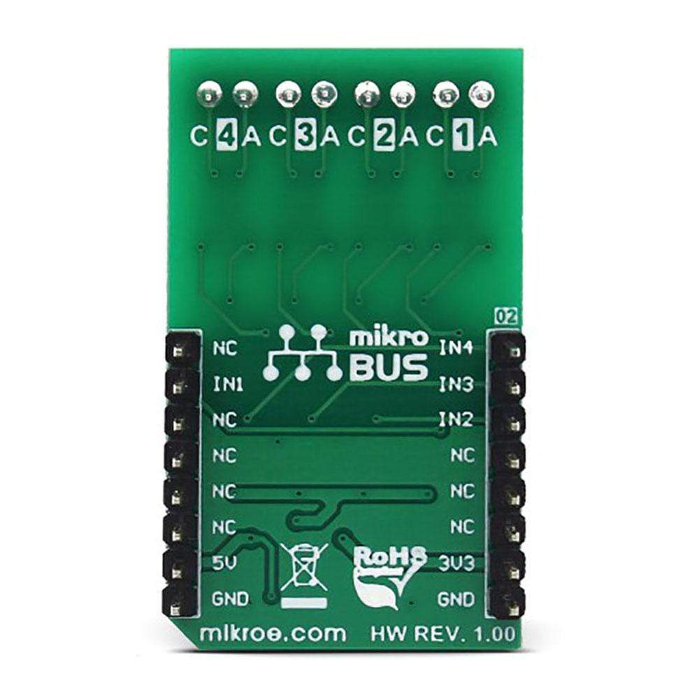
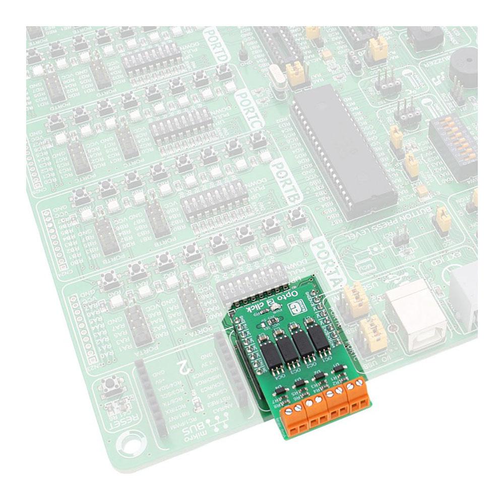
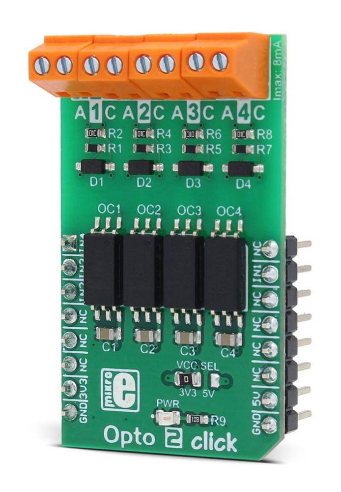
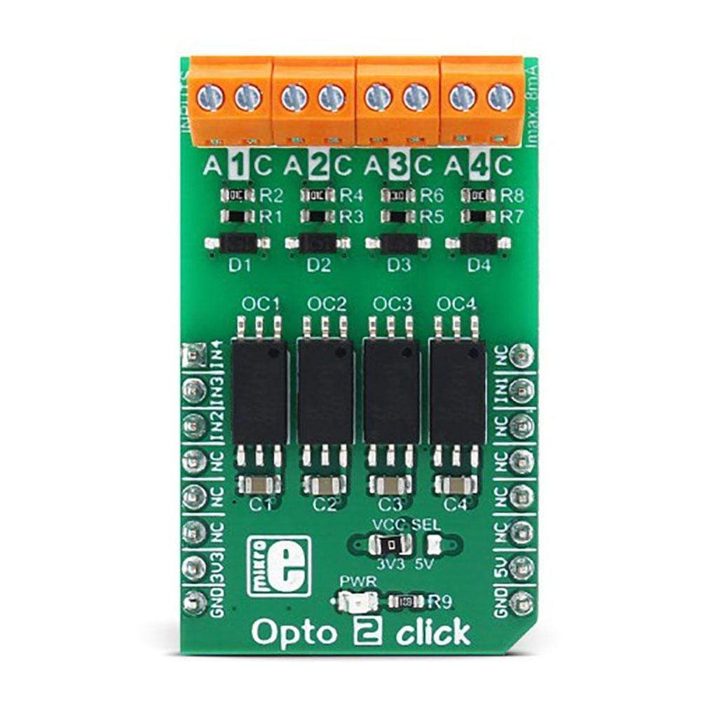
The Opto 2 Click Board™ is an optical isolator used to provide optical galvanic isolation of sensitive lines. The used optoisolation elements require a very low input current to be driven, down to 1.3mA (min). The speed of the internal optocoupler elements of the Opto 2 Click Board™ allows it to work with the signals up to 20MHz.
The Opto 2 Click Board™ can be used to provide galvanic isolation of the MCU pins, allowing driving by external components, while protecting it from surges up to 5kV on the driver side.
Downloads
L' Opto 2 Click Board™ est un isolateur optique utilisé pour assurer l'isolation galvanique optique des lignes sensibles. Les éléments d'opto-isolation utilisés nécessitent un courant d'entrée très faible pour être pilotés, jusqu'à 1,3 mA (min). La vitesse des éléments optocoupleurs internes de l' Opto 2 Click Board™ lui permet de fonctionner avec des signaux jusqu'à 20 MHz.
L' Opto 2 Click Board™ peut être utilisé pour fournir une isolation galvanique des broches du MCU, permettant le pilotage par des composants externes, tout en le protégeant des surtensions jusqu'à 5 kV côté pilote.
| General Information | |
|---|---|
Part Number (SKU) |
MIKROE-3015
|
Manufacturer |
|
| Physical and Mechanical | |
Weight |
0.022 kg
|
| Other | |
EAN |
8606018712946
|
Frequently Asked Questions
Have a Question?
Be the first to ask a question about this.