Carte à clic MIC23099
Overview
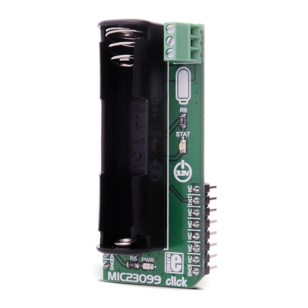
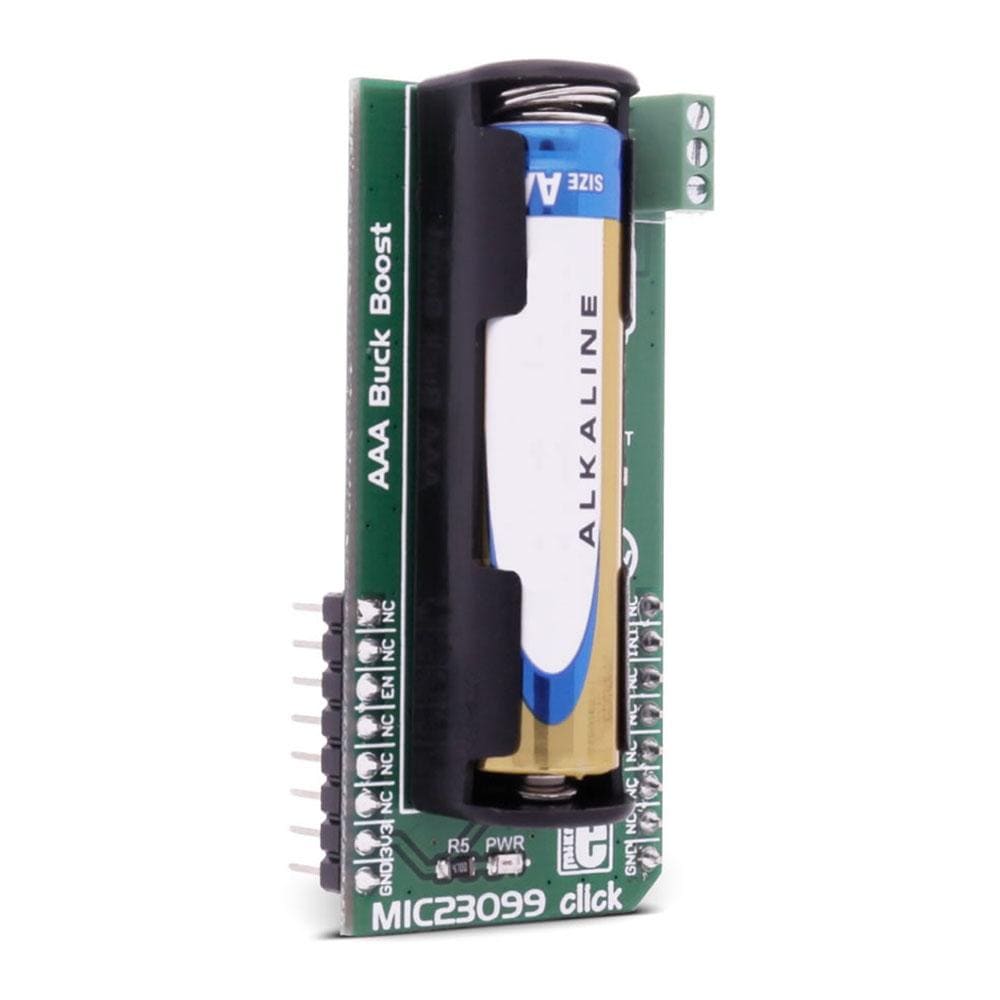
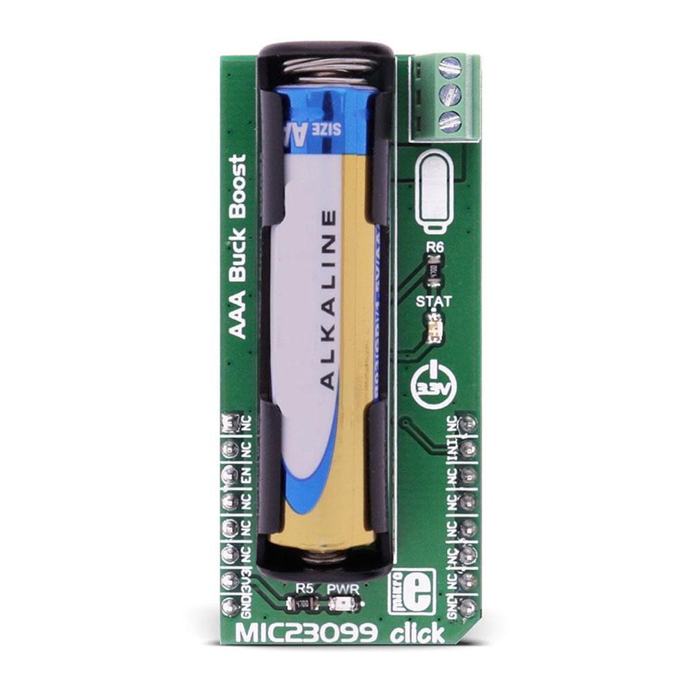
Le Click Board™ MIC23099 est équipé du MIC23099, un régulateur abaisseur/élévateur à cellule AA/AAA unique avec surveillance de la batterie. Le Click Board™ est conçu pour fonctionner sur une alimentation de 3,3 V.
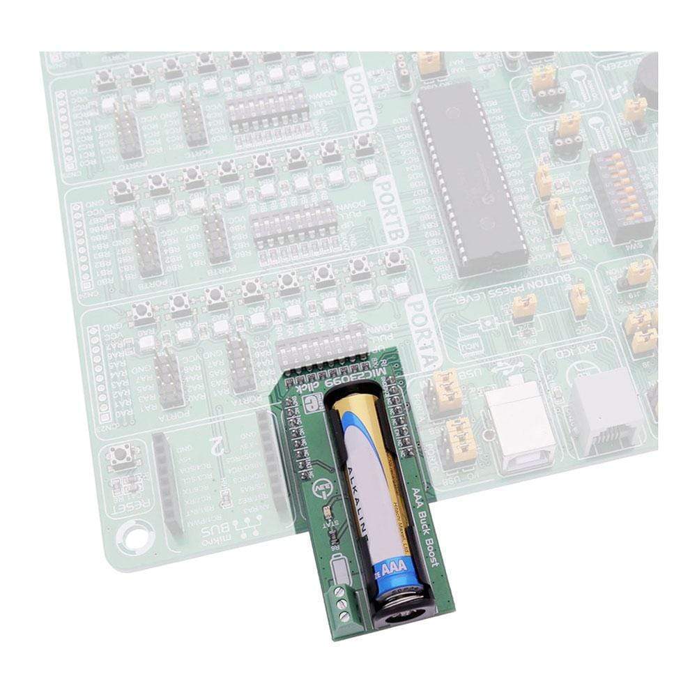
Il communique avec le microcontrôleur cible via les broches suivantes sur la ligne mikroBUS : CS, INT.
The MIC23099 Click Board™ carries the MIC23099, a single AA/AAA cell step-down/step-up regulator with battery monitoring. The MIC23099 Click Board™ is designed to run on a 3.3V power supply. It communicates with the target microcontroller over the following pins on the mikroBUS™ line: CS, INT.
How Does The MIC23099 Click Board™ wORK?
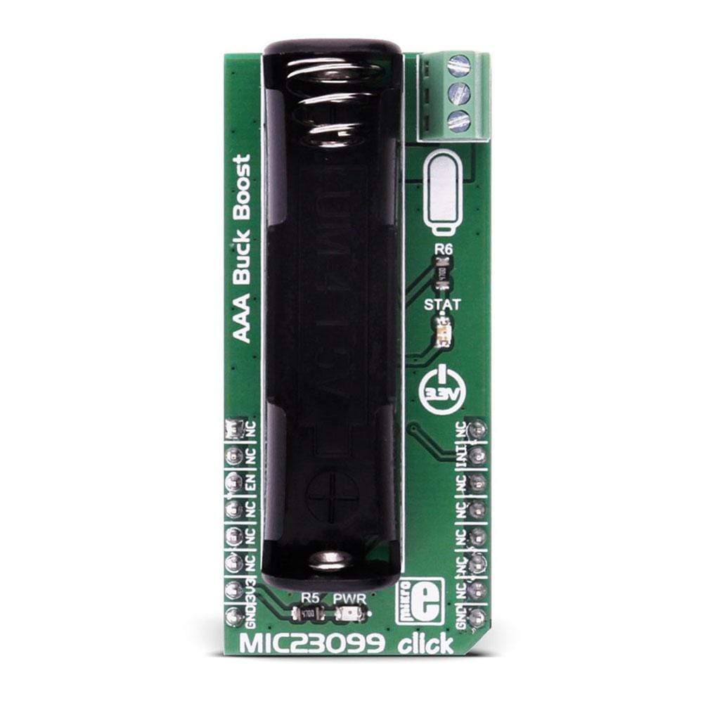
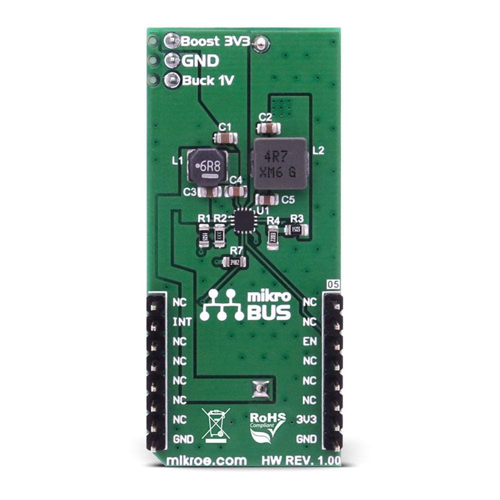
The MIC23099 Click Board™ has three screw terminals (Buck 1V, GND and Boost 3V3) which are outputs for connecting some external consumer.
The low-battery level is indicated by an onboard STAT LED.
Note: The MIC23099 is not a battery charger and it needs a battery to work properly. The battery is not included.
MIC23099 FEATURES
The MIC23099 is a high-efficiency, low-noise, dual output, integrated power management solution for single-cell alkaline or NiMH battery applications. To minimize switching artifacts in the audio band, both the converters are designed to operate with a minimum switching frequency of 80 kHz for the buck and 100 kHz for the boost. The high-current boost has a maximum switching frequency of 1 MHz, minimizing the solution footprint. The MIC23099 incorporates both battery management functions and fault protection.
SPECIFICATIONS
Type | Boost |
Applications | Voltage regulation for portable devices with AA or AAA batteries |
On-board modules | MIC23099 - a high-efficiency, low-noise, dual output, integrated power management solution for single-cell alkaline or NiMH battery applications |
Key Features | The low-battery level is indicated by an onboard STAT LED |
Interface | GPIO |
Compatibility | mikroBUS |
Click board size | L (57.15 x 25.4 mm) |
Input Voltage | 3.3V |
PINOUT DIAGRAM
This table shows how the pinout of the MIC23099 Click Board™ corresponds to the pinout on the mikroBUS™ socket (the latter shown in the two middle columns).
Notes | Pin | Pin | Notes | ||||
---|---|---|---|---|---|---|---|
NC | 1 | AN | PWM | 16 | NC | ||
NC | 2 | RST | INT | 15 | INT | Power Good output pin | |
Enable input pin | EN | 3 | CS | TX | 14 | NC | |
NC | 4 | SCK | RX | 13 | NC | ||
NC | 5 | MISO | SCL | 12 | NC | ||
NC | 6 | MOSI | SDA | 11 | NC | ||
Power supply | +3.3V | 7 | 3.3V | 5V | 10 | NC | |
Ground | GND | 8 | GND | GND | 9 | GND | Ground |
Software Support
Code examples for the MIC23099 Click Board™, written for MikroElektronika hardware and compilers are available on Libstock.
CODE SNIPPET
The following code snippet sets the EN pin to high, to enable the operation of this click.
01 sbit MIC23099_EN_PIN at GPIOD_ODR.B13; 02 void systemInit() 03 { 04 GPIO_Digital_Output( &GPIOD_ODR, _GPIO_PINMASK_13 ); 05 } 06 07 void MIC23099_Click_Init() 08 { 09 MIC23099_EN_PIN = 1; 10 } 11 12 void main() 13 { 14 systemInit(); 15 MIC23099_Click_Init(); 16 }
Frequently Asked Questions
Have a Question?
Be the first to ask a question about this.