Overview
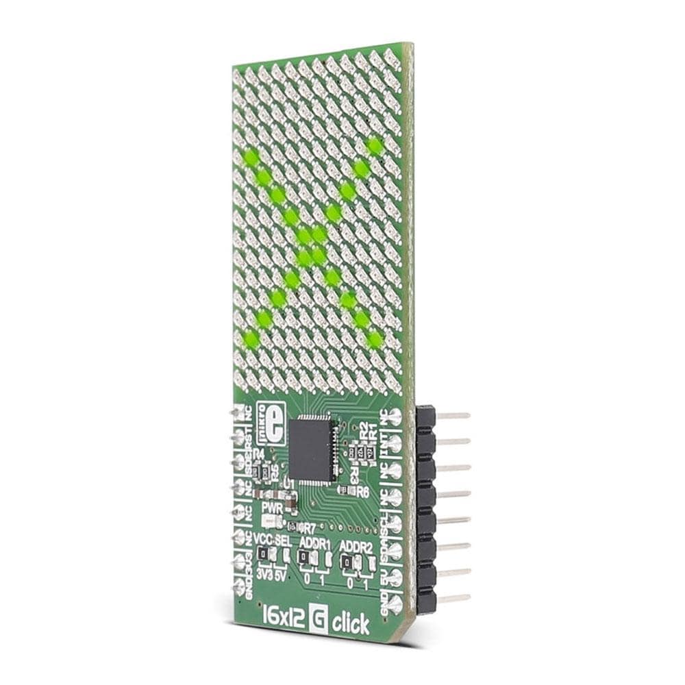
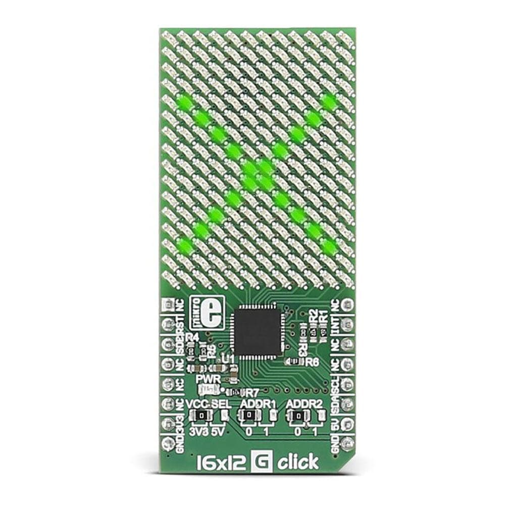
Introducing the 16x12 G Click Board, a versatile and dynamic addition to your electronics projects. This innovative Click Board™ features a 16x12 LED display coupled with the powerful IS31FL3733 matrix driver, offering you a wide range of creative possibilities.
One of the key features of the 16x12 G Click Board is its flexibility in power supply options. Whether you are working with a 3.3V or 5V power source, this Click Board™ is ready to deliver top-notch performance.
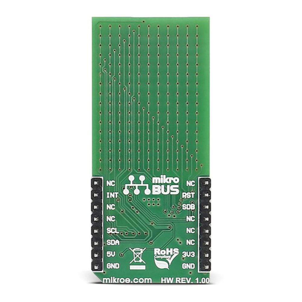
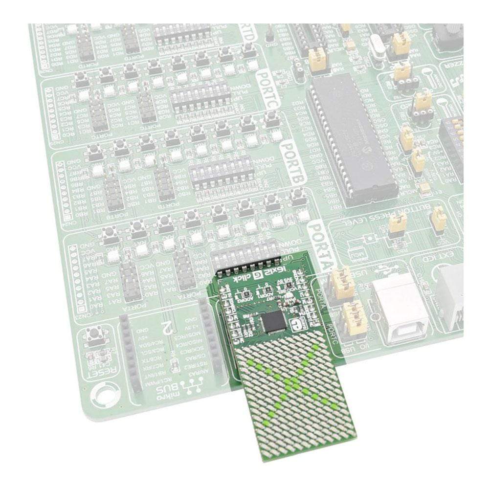
Designed for seamless integration, the 16x12 G Click Board communicates effortlessly with your target microcontroller through the I2C interface and specific pins on the MikroBUS line, including INT, RST, and CS.
Enhance your projects with the vibrant visual capabilities of the 16x12 G Click Board. Whether you are creating eye-catching displays or implementing innovative visual feedback systems, this Click Board™ is sure to impress with its clarity and precision.
Unleash your creativity and bring your ideas to life with the 16x12 G Click Board. Whether you are a seasoned electronics enthusiast or a beginner looking to explore the world of LED displays, this Click Board™ offers a user-friendly experience that is both engaging and rewarding.
Experience the convenience and power of the 16x12 G Click Board today. Elevate your projects with superior visual displays and seamless integration, all in one compact and reliable package.
Downloads
Présentation du Click Board 16x12 G, un ajout polyvalent et dynamique à vos projets électroniques. Ce Click Board™ innovant est doté d'un écran LED 16x12 couplé au puissant pilote de matrice IS31FL3733, vous offrant un large éventail de possibilités créatives.
L'une des caractéristiques clés de la carte Click Board 16x12 G est sa flexibilité en termes d'options d'alimentation. Que vous travailliez avec une source d'alimentation de 3,3 V ou de 5 V, cette carte Click Board™ est prête à offrir des performances de premier ordre.
Conçue pour une intégration transparente, la carte Click 16x12 G communique sans effort avec votre microcontrôleur cible via l'interface I2C et des broches spécifiques sur la ligne MikroBUS, notamment INT, RST et CS.
Améliorez vos projets avec les capacités visuelles dynamiques du Click Board 16x12 G. Que vous créiez des affichages accrocheurs ou que vous mettiez en œuvre des systèmes de rétroaction visuelle innovants, ce Click Board™ impressionnera à coup sûr par sa clarté et sa précision.
Libérez votre créativité et donnez vie à vos idées avec le Click Board 16x12 G. Que vous soyez un passionné d'électronique chevronné ou un débutant souhaitant explorer le monde des écrans LED, ce Click Board™ offre une expérience conviviale à la fois engageante et enrichissante.
Découvrez dès aujourd'hui la commodité et la puissance du tableau Click Board 16x12 G. Améliorez vos projets avec des affichages visuels de qualité supérieure et une intégration transparente, le tout dans un seul ensemble compact et fiable.
| General Information | |
|---|---|
Part Number (SKU) |
MIKROE-2758
|
Manufacturer |
|
| Physical and Mechanical | |
Weight |
0.022 kg
|
| Other | |
Country of Origin |
|
HS Code Customs Tariff code
|
|
EAN |
8606018711468
|
Warranty |
|
Frequently Asked Questions
Have a Question?
Be the first to ask a question about this.

