

Mikroelektronika d.o.o.
Carte RS485 2 Click
Carte RS485 2 Click
SKU: MIKROE-2700
Impossible de charger la disponibilité du service de retrait


Overview
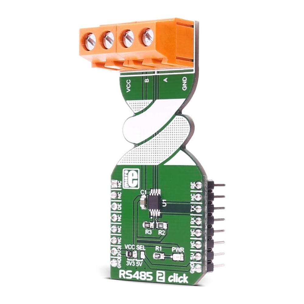
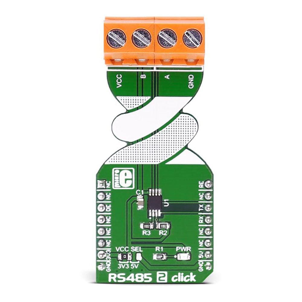
The RS485 2 Click Board™ carries the MAX3471 half-duplex transceiver intended for lithium battery-powered RS-485/RS-422 applications.
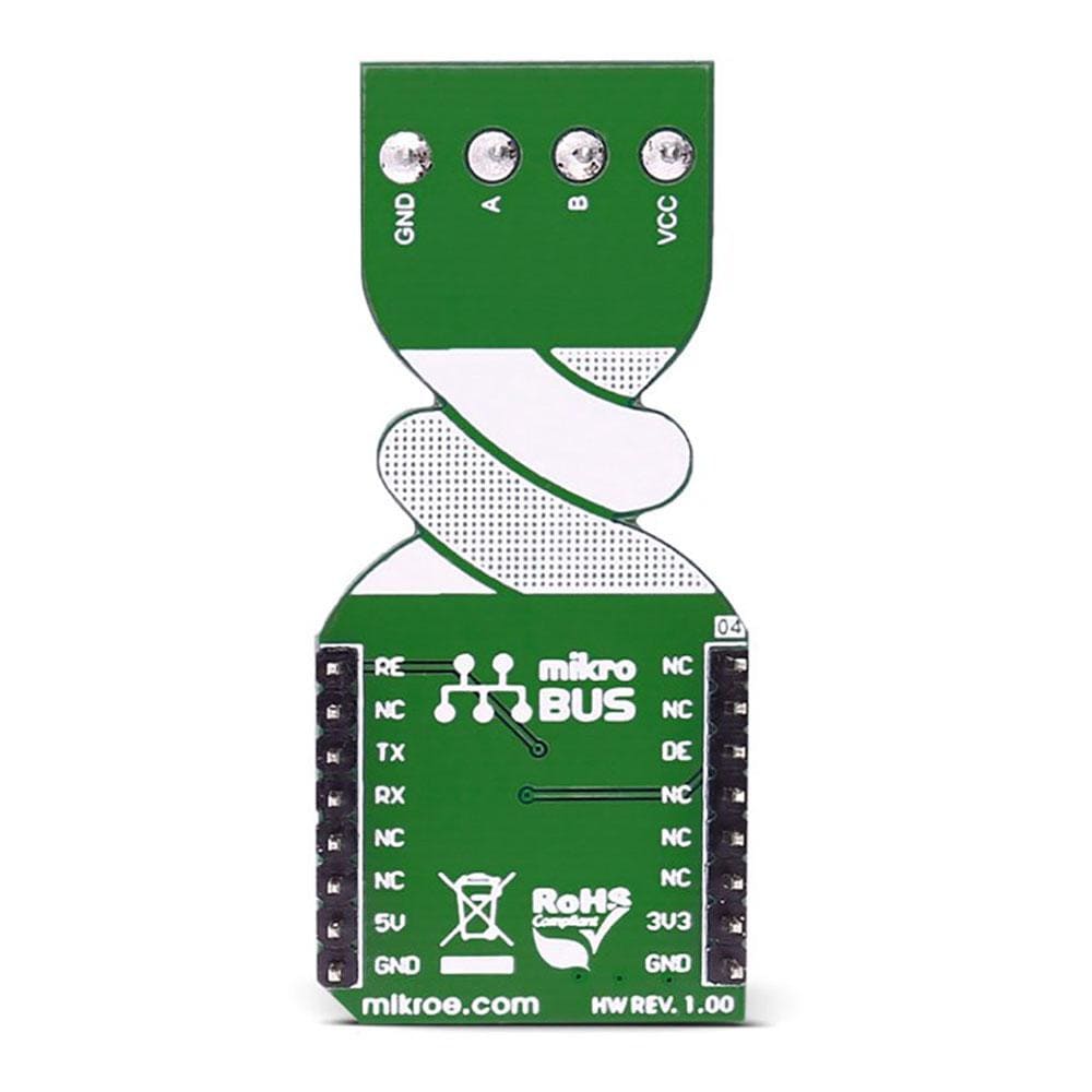
The RS485 2 Click Board™ is designed to run on either a 3.3V or 5V power supply. It communicates with the target microcontroller over the UART interface with additional functionality provided by the following pins on the MikroBUS line: PWM, CS.
Downloads
La carte RS485 2 Click Board™ intègre l'émetteur-récepteur semi-duplex MAX3471 destiné aux applications RS-485/RS-422 alimentées par batterie au lithium.
La carte RS485 2 Click Board™ est conçue pour fonctionner sur une alimentation 3,3 V ou 5 V. Elle communique avec le microcontrôleur cible via l'interface UART avec des fonctionnalités supplémentaires fournies par les broches suivantes sur la ligne MikroBUS : PWM, CS.
| General Information | |
|---|---|
Part Number (SKU) |
MIKROE-2700
|
Manufacturer |
|
| Physical and Mechanical | |
Weight |
0.025 kg
|
| Other | |
EAN |
8606018710935
|
Frequently Asked Questions
Have a Question?
Be the first to ask a question about this.