Passer aux informations produits
1 de 4

Mikroelektronika d.o.o.

Carte à clic pour moteur à courant continu 5

Carte à clic pour moteur à courant continu 5

SKU: MIKROE-2699
Prix habituel
€16,95 EUR hors taxes
Prix habituel Prix promotionnel
€16,95 EUR hors taxes
En vente Épuisé
Frais d'expédition calculés à l'étape de paiement.
If no stock shown above, check availability
Afficher tous les détails
} ] }

Overview

La carte DC Motor 5 Click Board™ intègre le pilote de grille de moteur CC à balais DRV8701 de Texas Instruments.

Le DC Motor 5 Click Board™ est conçu pour fonctionner sur une alimentation externe. Il communique avec le microcontrôleur cible via les broches suivantes de la ligne MikroBUS : AN, RST, CS, PWM et INT.

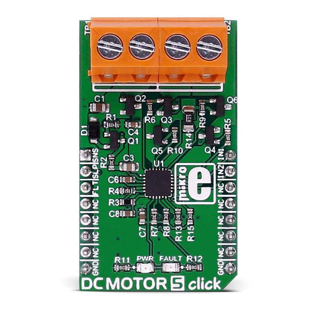
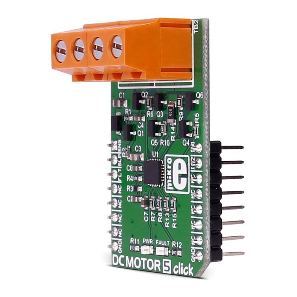
The DC Motor 5 Click Board™ carries the DRV8701 brushed DC motor gate driver from Texas Instruments.
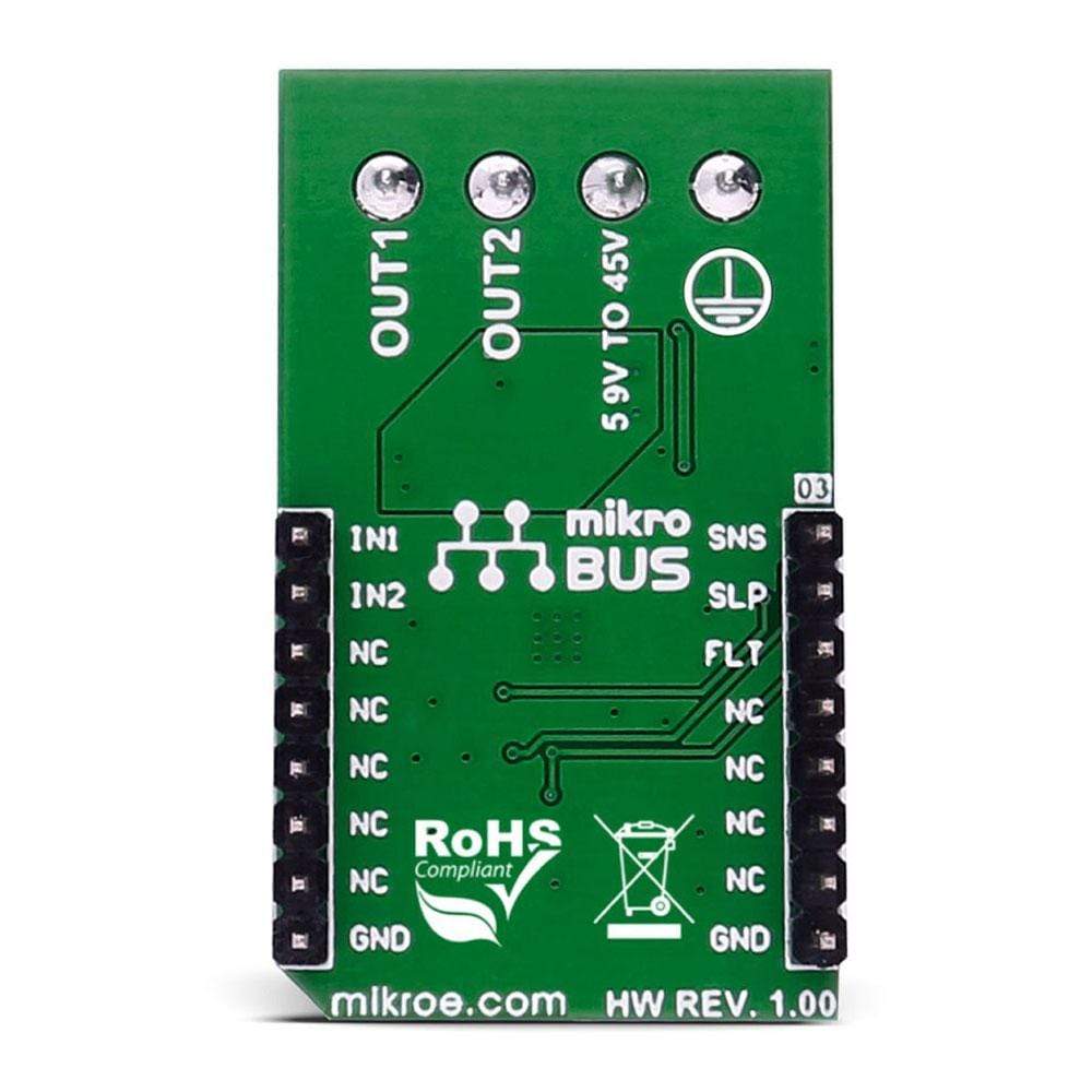
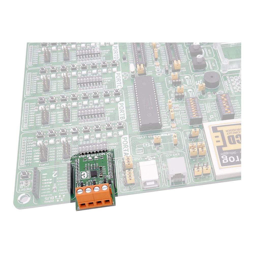
 The click is designed to run on an external power supply. It communicates with the target MCU over the following pins on the mikroBUS™ line: AN, RST, CS, PWM, and INT.

DRV8701 DRIVER FEATURES

 The DRV8701 is an H-bridge gate driver (also called a pre-driver or controller). The device integrates FET gate drivers in order to control four external NMOS FETs. The device can be powered with a supply voltage between 5.9V and 45V.

Internal protection functions are provided: under-voltage lockout, charge pump faults, overcurrent shutdown, short-circuit protection, pre-driver faults, and overtemperature.

How Does The DC Motor 5 Click Board™ Work?

The motor's velocity and direction can be adjusted with two PWM input signal's.
DC motor 5

SPECIFICATIONS

Type Brushed
Applications Industrial brushed-DC motors, robotics, home automation, etc.
On-board modules DRV8701 Brushed DC Motor Full-Bridge Gate Driver
Key Features supply voltage between 5.9V and 45V
Interface GPIO
Compatibility mikroBUS
Click board size M (42.9 x 25.4 mm)
Input Voltage External

PINOUT DIAGRAM

This table shows how the pinout of the DC Motor 5 Click Board™ corresponds to the pinout on the mikroBUS™ socket (the latter shown in the two middle columns).

Notes Pin Mikrobus logo.png Pin Notes
Sense comparator output SNSO 1 AN PWM 16 IN1 Input signal 1
Device sleep mode SLEEP 2 RST INT 15 IN2 Input signal 2
Fault indication pin FAULT 3 CS TX 14 NC
NC 4 SCK RX 13 NC
NC 5 MISO SCL 12 NC
NC 6 MOSI SDA 11 NC
NC 7 3.3V 5V 10 NC
Ground GND 8 GND GND 9 GND Ground

BUTTONS AND LEDS

Designator Name Type Description
LD1 PWR LED Power Indication LED
TB1 VM CD Voltage input connector
TB2 Out_M CD Motor connector

MAXIMUM RATINGS

Description Min Typ Max Unit
Supply VOltage 5.9 45 V
Source Current 6 150 mA
Sink Current 12.5 300 mA
Applied PWM signal 100 kHz
Operating ambient temperature -40 125


Frequently Asked Questions

Have a Question?

Be the first to ask a question about this.

Ask a Question

Customer Reviews

Be the first to write a review
0%
(0)
0%
(0)
0%
(0)
0%
(0)
0%
(0)