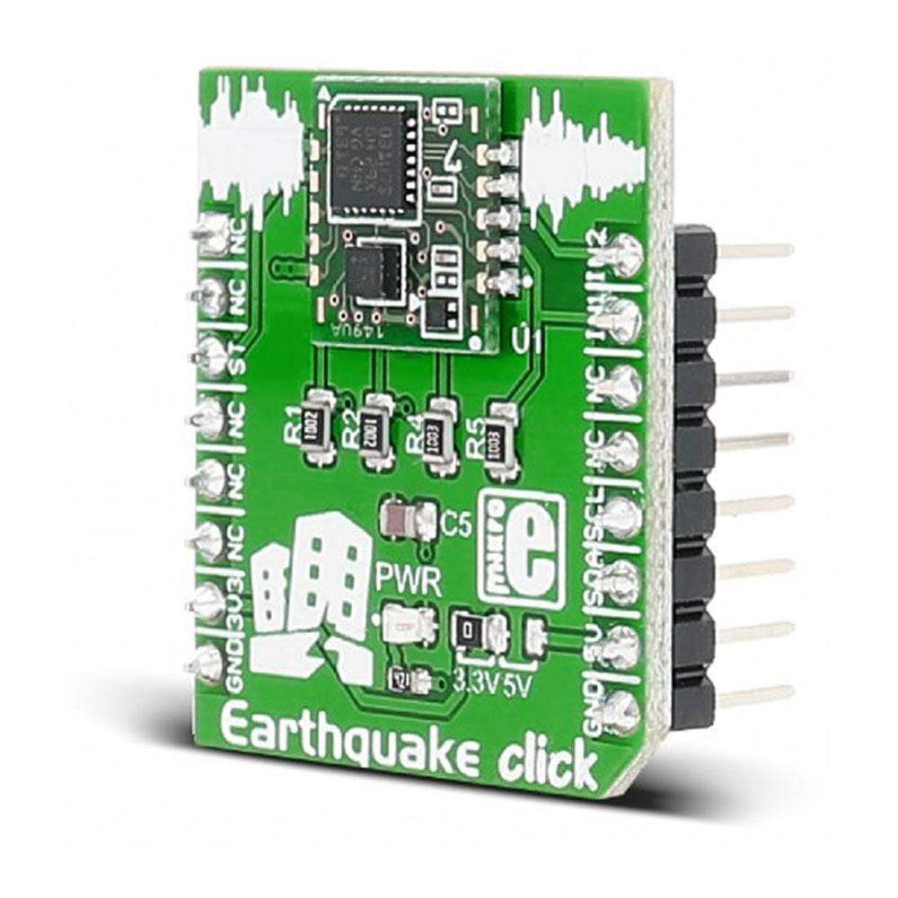
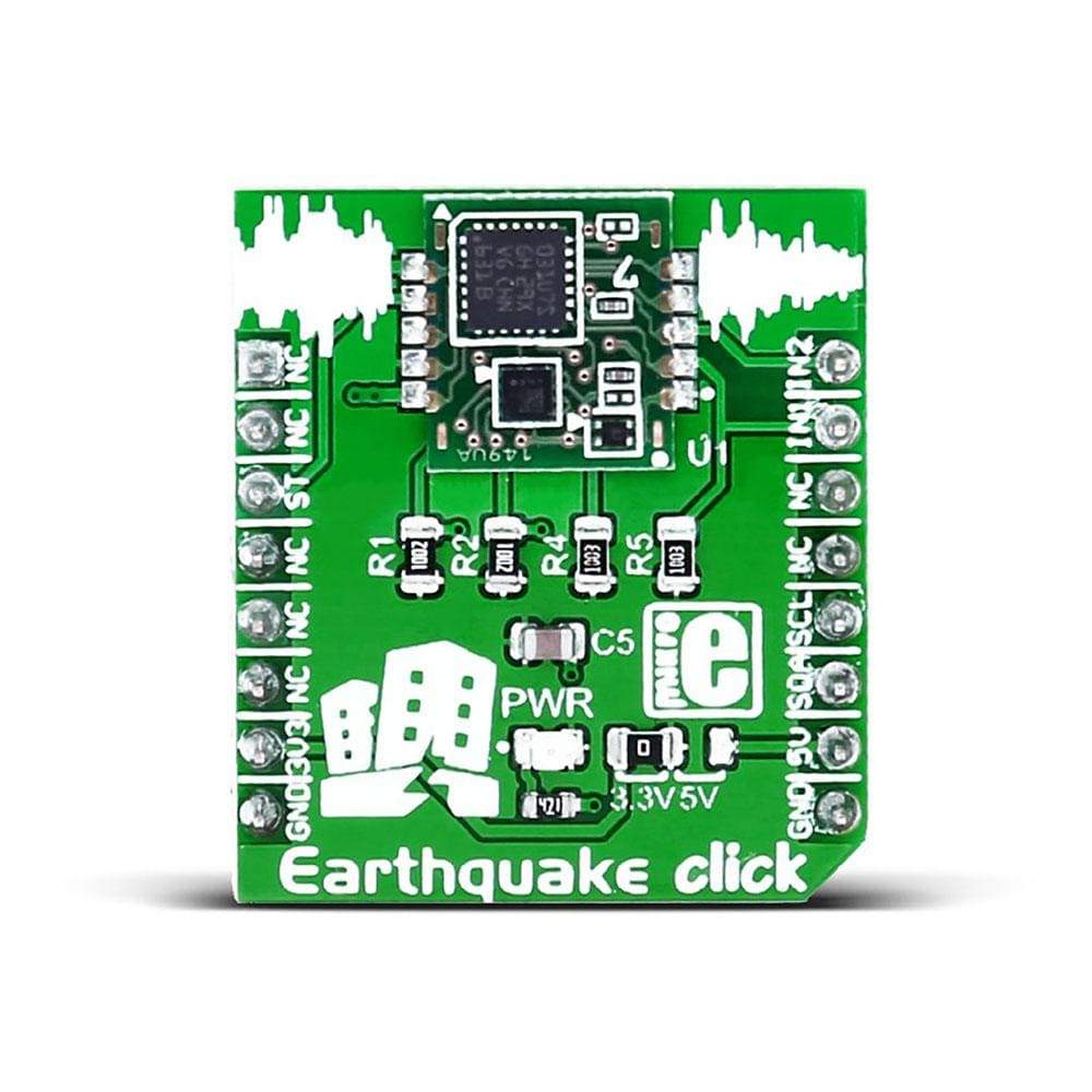
Tableau à cliquer sur les tremblements de terre
Overview
Le Click Board™ Earthquake est basé sur le D7S, le plus petit capteur sismique de haute précision au monde d'Omron. Le Click Board™ est conçu pour fonctionner sur une alimentation 3,3 V ou 5 V. Il communique avec le microcontrôleur cible via l'interface I2C, avec des fonctionnalités supplémentaires fournies par les broches suivantes sur la ligne MikroBUS : PWM, INT, CS.
Lorsqu'un tremblement de terre se produit avec une intensité sismique équivalente à 5 ou plus sur l'échelle d'intensité sismique JMA (Agence météorologique japonaise), le D7S activera la sortie d'arrêt pour avertir l'utilisateur qu'un tremblement de terre s'est produit.
The Earthquake Click Board™ carries D7S, the world's smallest high-precision seismic sensor from Omron. The Earthquake Click Board™ is designed to run on either 3.3V or 5V power supply. It communicates with the target MCU over I2C interface, with additional functionality provided by the following pins on the mikroBUS™ line: PWM, INT, CS.
When an earthquake occurs with a seismic intensity equivalent to 5 Upper or higher on the JMA (Japan Meteorological Agency) Seismic Intensity Scale, the D7S will activate the shutoff output to notify the user that an earthquake has occurred.
How Does The Earthquake Click Board™ Work?
Using the SI (spectral intensity) value, which has a high correlation with the seismic intensity scale that indicates the magnitude of an earthquake, provides higher-precision judgment of seismic intensity scales.
The 3-axis acceleration Sensor and Omron's unique SI value calculation algorithm achieve high precision and low consumption. (Higher degree of freedom for incorporation into devices and prolonged operation on battery power).
Shutoff output terminal (INT1) operates equivalent to a conventional mechanical vibration sensor and ensures compatibility with mechanical vibration sensors.
I2C interface is able to obtain earthquake-related information from the sensor with communications from external devices.
SPECTRAL INTENSITY
The SI value (or spectral intensity) is equivalent to the magnitude of the destructive energy imposed by seismic motion on structures.
LOW POWER CONSUMPTION
The power consumption during standby is 90 μA or less. On average, during processing, the sensor uses around 300 μA.
JMA SEISMIC INTENSITY SCALE
JMA or Japan Meteorological Agency intensity scale is used in Japan and Taiwan to measure the intensity of earthquakes. The scale goes from 0 to 7. The level 5 on this scale indicates when objects inside a house start falling down, like books from the shelf, dishes in a cupboard, cracks are formed on walls, etc.
SPECIFICATIONS
Type | Motion,Vibration |
Applications | Vibration sensor, fire prevention systems, electricity meters, gas meters, chemical plants, bridges, tunnels, etc. |
On-board modules | The D7S, world's smallest high-precision seismic sensor |
Key Features | Low power consumption, Acceleration Detection Range −2,000 to 2,000 gal, Shutoff Output (INT1) Output at seismic intensity level 5 or higher |
Interface | GPIO,I2C |
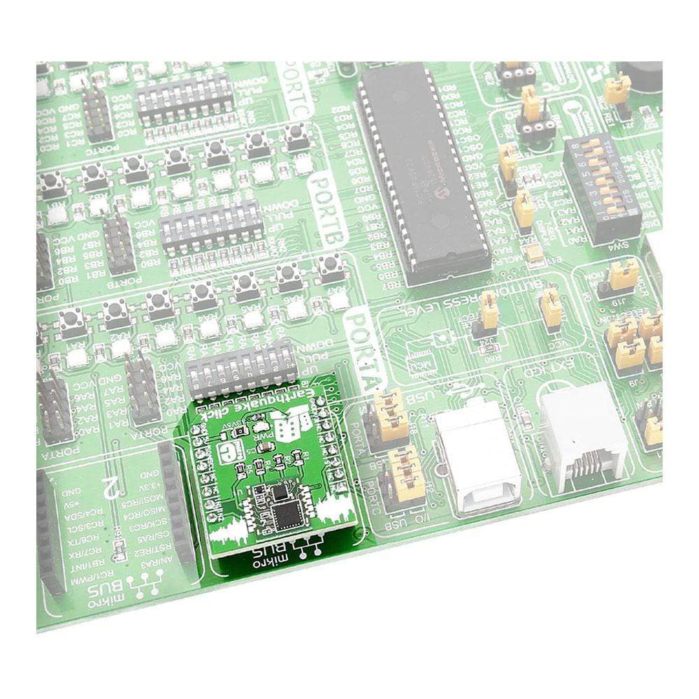
Compatibility | mikroBUS |
Click board size | S (28.6 x 25.4 mm) |
Input Voltage | 3.3V or 5V |
PINOUT DIAGRAM
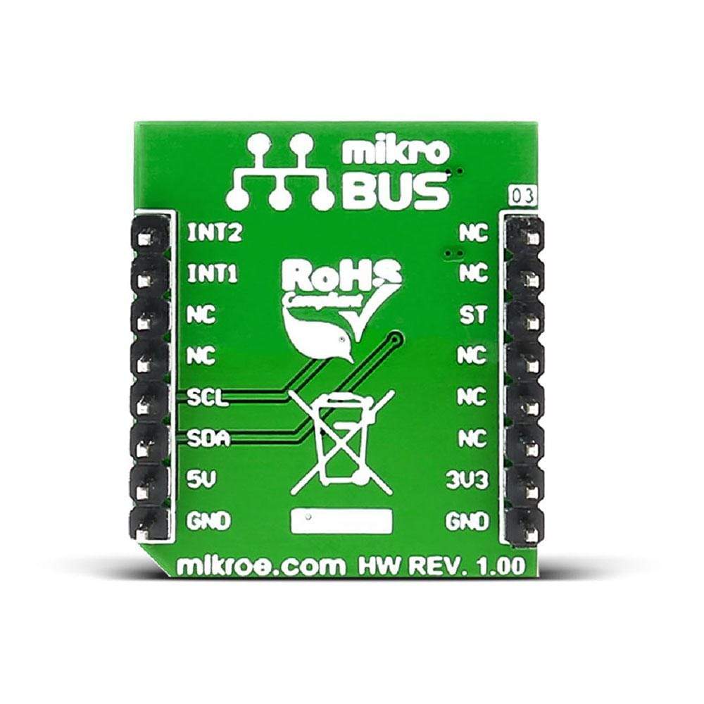
This table shows how the pinout of the Earthquake Click Board™ corresponds to the pinout on the mikroBUS™ socket (the latter shown in the two middle columns).
Notes | Pin | Pin | Notes | ||||
---|---|---|---|---|---|---|---|
NC | 1 | AN | PWM | 16 | INT2 | Processing notification output | |
NC | 2 | RST | INT | 15 | INT1 | Shutoff output | |
Initial setting input | SETTING | 3 | CS | TX | 14 | NC | |
NC | 4 | SCK | RX | 13 | NC | ||
NC | 5 | MISO | SCL | 12 | SCL | I2C clock | |
NC | 6 | MOSI | SDA | 11 | SDA | I2C data | |
Power supply | +3.3V | 7 | 3.3V | 5V | 10 | +5V | Power supply |
Ground | GND | 8 | GND | GND | 9 | GND | Ground |
MAXIMUM RATINGS
Description | Min | Typ | Max | Unit |
---|---|---|---|---|
Power Supply Voltage | -0.3 | 6.0 | V | |
Average Current Consumption during Processing | 300 | uA | ||
Operating Temperature | -30 | 70 | ℃ |
JUMPERS AND SETTINGS
Designator | Name | Default Position | Default Option | Description: |
---|---|---|---|---|
JP1 | PWR.SEL. | Left | 3.3V | Power Supply Voltage Selection 3.3V/5V, left position 3.3V, right position 5V |
Software Support
Code examples for the Earthquake Click Board™, written for MikroElektronika hardware and compilers are available on Libstock.
CODE SNIPPET
The following code calls initialization functions, and then checks the status and SI value registers every 5 seconds.
01 void main(){ 02 03 system_init (); 04 eq_init(0x55); 05 06 while (1) 07 { 08 UART_Write_Text( "rn Status: " ); 09 si_value = eq_read_status (); 10 IntToStr( si_value, uart_text ); 11 UART_Write_Text(uart_text); 12 UART_Write( 32 ); 13 14 /*reads strongest SI value detected during current quake */ 15 UART_Write_Text( " Current SI value: " ); 16 si_value = eq_si_rs (); 17 IntToStr( si_value, uart_text ); 18 UART_Write_Text(uart_text); 19 UART_Write( 32 ); 20 21 Delay_ms (5000); 22 } 23 }
Frequently Asked Questions
Have a Question?
Be the first to ask a question about this.