Carte Tamper 2 Click
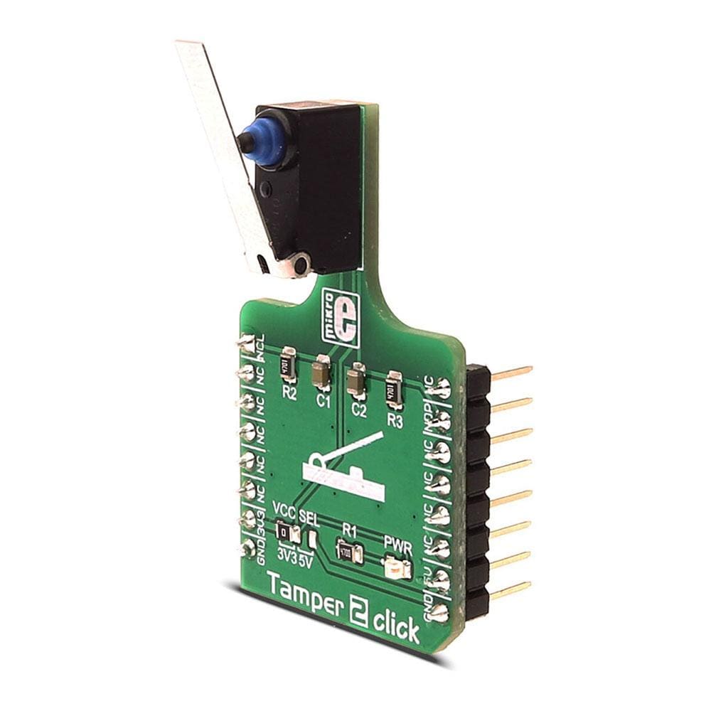
Le Tamper 2 Click Board™ contient un commutateur à levier D2HW-A221D d'Omron, qui émet un signal dans les deux positions - enfoncée et relâchée. Les commutateurs Omron, également connus sous le nom de micro-interrupteurs, sont réputés pour leur fiabilité et leur endurance. Le PCB de ce Click Board™ est conçu de manière à ce que le levier du micro-interrupteur soit facilement accessible, ce qui rend le Click Board™ utile pour toutes sortes d'applications différentes, où des commutateurs précis à deux positions sont nécessaires. Les broches NO (normalement ouvertes) et NC (normalement fermées) du micro-interrupteur sont acheminées vers mikroBUS, ce qui permet de le connecter facilement au microcontrôleur.
Les commutateurs de ce type sont largement utilisés dans de nombreuses applications différentes. L'utilisation la plus courante du Tamper 2 Click Board™ est la détection d'ouverture ou de fermeture de porte, la détection de fin de course d'un actionneur linéaire, d'un dispositif d'entrée de code Morse, etc.
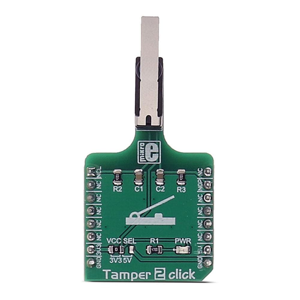
The Tamper 2 Click Board™ contains a levered D2HW-A221D switch by Omron, which outputs signal in both positions - pressed and released. Omron switches, also known as microswitches, are well renowned for their reliability and endurance. The PCB of this click is designed so that the lever of the microswitch is easily accessible, making the click useful for all kinds of different applications, where precise, two position switches are required. Both the NO (Normally Open) and NC (Normally Closed) pins of the microswitch are routed to mikroBUS™, so it can be easily connected to the microcontroller.
Switches of this kind are widely used in many different applications. The most common use of the Tamper 2 Click Board™ is door opening or closing detection, detecting the end of travel of a linear actuator, a Morse code input device and so on.
How Does The Tamper 2 Click Board™ Work?
The Tamper 2 Click Board™ contains a levered D2HW-A221D microswitch by Omron, specifically positioned on the board so it is easily accessible for interacting with various objects that could press the lever, activating the microswitch that way. The microswitch is actuated by applying very little physical force, using a tipping-point mechanism which results in fast and reliable snap-in action. It also has both NC and NO contacts routed to the mikroBUS™ so both states of the switch can be detected. Both lines are equipped with the RC filters, which serve as debouncing elements for the switch and also to pull down the lines when they are left afloat. This way, the contact bouncing is reduced even further, resulting in an accurate detection of the switching event.
The switch itself is very endurable and its rated up to 42VDC / 0.5A, also can endure a very high number of switching cycles – up to 1000000.
The Tamper 2 Click Board™ also features an onboard jumper selector, which is used to select the voltage level that is connected to the microswitch input pin, making it usable for both 3V3 and 5V capable microcontroller pins.
SPECIFICATIONS
Type | Pushbutton/Switches |
Applications | Door opening or closing detection, detecting the end of travel of a linear actuator, a Morse code input device, etc. |
On-board modules | D2HW-A221D switch by Omron |
Key Features | High-quality Omron microswitch, high mechanical and electrical durability, debouncing features |
Interface | GPIO |
Compatibility | mikroBUS |
Click board size | S (28.6 x 25.4 mm) |
Input Voltage | 3.3V or 5V |
PINOUT DIAGRAM
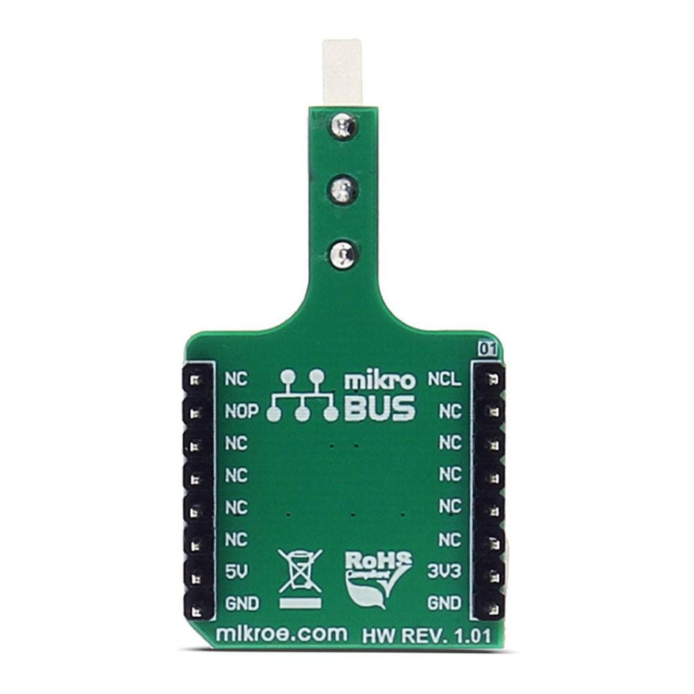
This table shows how the pinout of the Tamper 2 Click Board™ corresponds to the pinout on the mikroBUS™ socket (the latter shown in the two middle columns).
Notes | Pin | Pin | Notes | ||||
---|---|---|---|---|---|---|---|
Normally closed | NCL | 1 | AN | PWM | 16 | NC | |
NC | 2 | RST | INT | 15 | NOP | Normally open | |
NC | 3 | CS | RX | 14 | NC | ||
NC | 4 | SCK | TX | 13 | NC | ||
NC | 5 | MISO | SCL | 12 | NC | ||
NC | 6 | MOSI | SDA | 11 | NC | ||
Power supply | 3V3 | 7 | 3.3V | 5V | 10 | 5V | Power supply |
Ground | GND | 8 | GND | GND | 9 | GND | Ground |
TAMPER 2 CLICK ELECTRICAL SPECIFICATIONS
Description | Min | Typ | Max | Unit |
---|---|---|---|---|
Contact resistance | 100 | mΩ | ||
Mechanical durability (30 operations/min) | 1 milion | cycles | ||
Electrical durability (20 operations/min) | 10000 | cycles |
ONBOARD SETTINGS AND INDICATORS
Label | Name | Default | Description |
---|---|---|---|
JP1 | VCC SEL | Left | Power supply voltage selection. Left position 3V3, right position 5V |
LD1 | Power LED | Power LED indicates that the click is powered on | |
S1 | SWITCH | Onboard switch |
Software Support
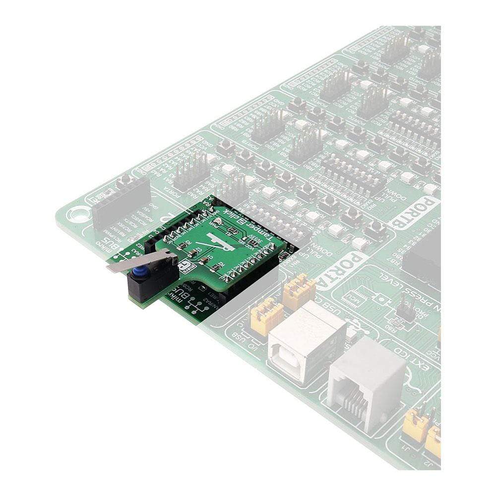
We provide an example for the Tamper 2 Click Board™ on our LibStock page, as well as a demo application (example), developed using MikroElektronika compilers. The demo can run on all the main MikroElektronika development boards.
Example Description
The application is composed of three sections :
- System Initialization - Initializes UART module used for data logging
- Application Initialization - Initializes Tamper 2 click GPIO pins
- Application Task - Check the state of both GPIO pins and reports current state by logging information to UART
void Tamper_2_click_Task() { if (TAMPER_ON_STATE == 1) { UART0_Write_text("Tamper 2 click is in ON statern"); } if (TAMPER_OFF_STATE == 1) { UART0_Write_text("Tamper 2 click is in OFF statern"); } Delay_ms(500); }
The example code for all architectures and compilers, and ready to use projects can be found on our LibStock page.
Other mikroE Libraries used in the example:
- UART
Additional Notes and Information
Depending on the development board you are using, you may need USB UART click, USB UART 2 click or RS232 click to connect to your PC, for development systems with no UART to USB interface available on the board. The terminal available in all MikroElektronika compilers, or any other terminal application of your choice, can be used to read the message.
Carte Tamper 2 Click
Frequently Asked Questions
Have a Question?
Be the first to ask a question about this.