Panneau de clic pour thermostat
Overview
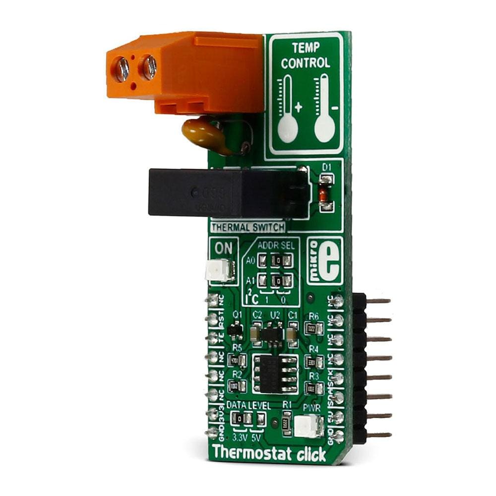
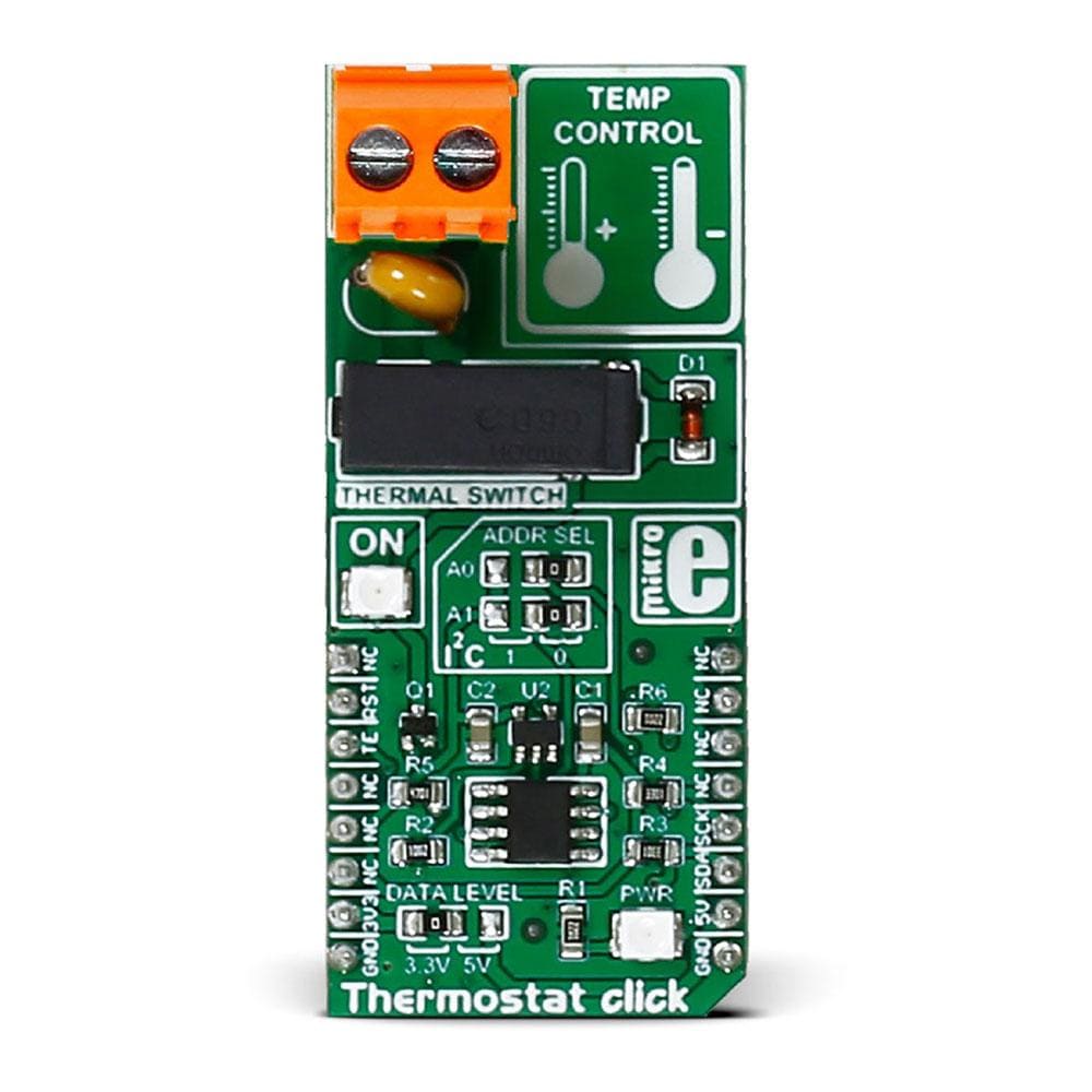
Le Thermostat Click Board™ est basé sur le capteur de température numérique Maxim MAX7502 IC. Il fournit également une sortie d'alarme/d'interruption/d'arrêt en cas de surchauffe et un tampon de bus unique SN74LVC1G126 de Texas Instruments.
Le circuit intégré MAX7502 peut mesurer des températures de -25 °C à +100 °C, avec une précision de ± 1,5 °C.
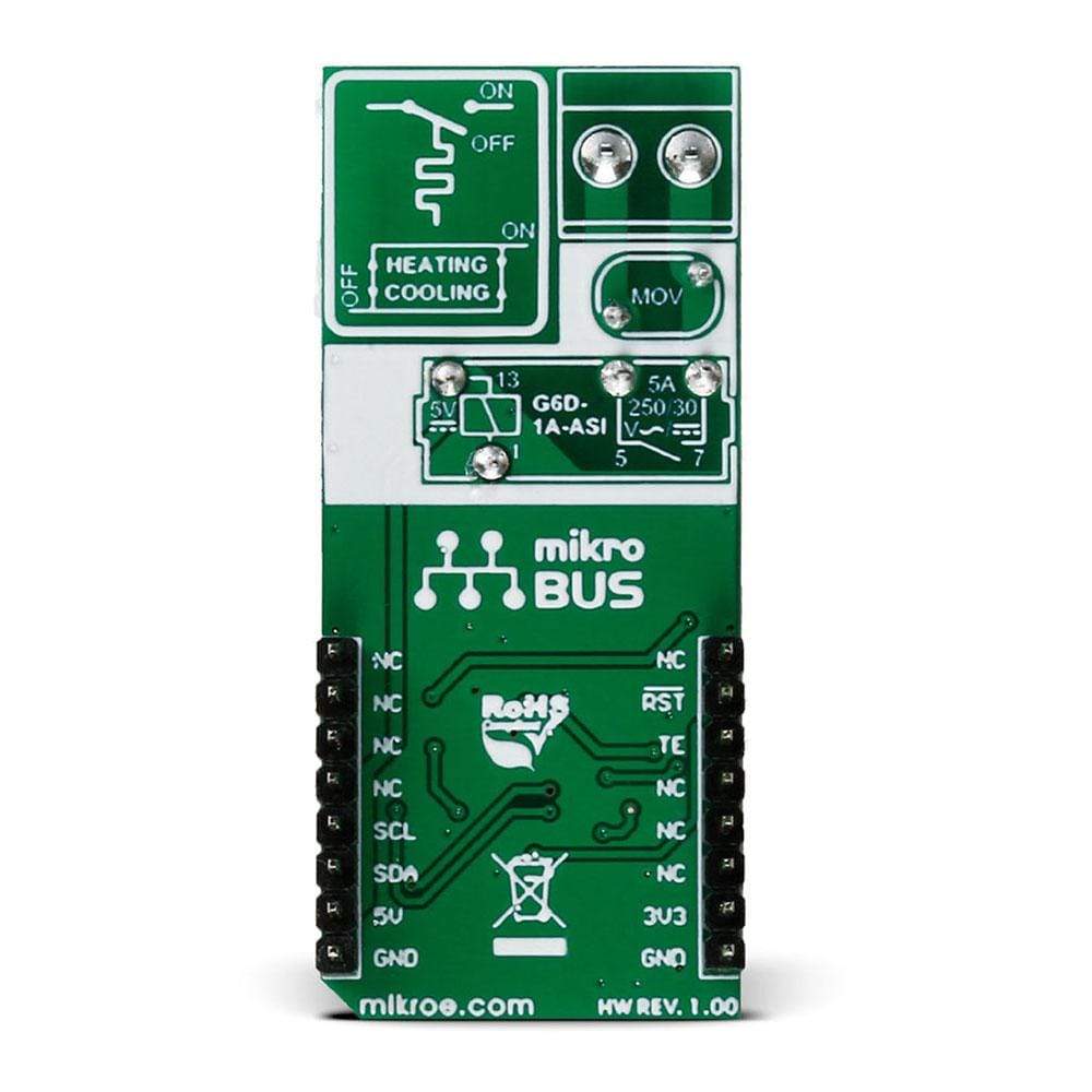
Le relais de puissance PCB G6D peut contrôler des charges jusqu'à 5 A, 250 V CA/30 V CC .
If you need a temperature sensor and relay in one device, you should look no further than the Thermostat Click Board™. It can be used to measure environmental temperature and to directly switch ON/OFF cooling and heating devices, performing all the functions of a thermostat.
The Thermostat Click Board™ carries the MAX7502 IC digital temperature sensor, that also provides an overtemperature alarm/interrupt/shutdown output, and an SN74LVC1G126 single bus buffer from Texas Instruments. MAX7502 IC can measure temperatures from -25°C to +100°C, within the accuracy of ±1.5°C.
The G6D PCB power relay can control up to 5A, 250V AC/30V DC loads.
The click runs on either 3.3V or 5V power supply and communicates with the target MCU over I2C interface.
TEMPERATURE RANGE
The IC can measure temperatures from -25°C to +100°C, within the accuracy of ±1.5°C.
MAX7502 TEMPERATURE SENSOR
MAX7502 temperature sensor measures temperature, converts the data into digital form using a sigma-delta ADC, and communicates the conversion results through an I2C-compatible 2-wire serial interface.
It accepts standard I2C commands to read the data, set the overtemperature alarm trip thresholds, and configure other characteristics.
LOW POWER CONSUMPTION
The MAX7502 temperature sensor typically uses only around 250 µA, and in shutdown mode around 3 µA. With such low power consumption, it is very suitable for home automation devices.
ENABLE/DISABLE THERMOSTAT FUNCTIONALITY
There is also the TE (thermostat enable) pin on the mikroBUS™ pin socket for enabling (high level) or disabling (low) of the thermostat functionality. This is accomplished via the SN74LVC1G126 single bus buffer with 3-state output IC, which serves as an electronic switch between temperature sensor IC output pin and the relay driver circuit.
This way the relay can be permanently disconnected from the sensor IC output. A feature like this can be useful when the sensor IC is only used as an measuring device, or if the thermostat needs to be temporarily disabled.
APPLICATION
HVAC systems, heating systems, cooling systems, simple interrupt ON/OFF temp control, hysteresis controller, etc.
SPECIFICATIONS
Type | Temperature & humidity |
Applications | HVAC systems, heating systems, cooling systems, simple interrupt ON/OFF temp control, hysteresis controller, etc. |
On-board modules | MAX7502 IC digital temperature sensor |
Key Features | MAX7502 temperature sensor, SN74LVC1G126 single bus buffer, G6D PCB power relay, I2C interface, either 3.3V or 5V power supply, |
Interface | GPIO,I2C |
Compatibility | mikroBUS |
Click board size | L (57.15 x 25.4 mm) |
Input Voltage | 3.3V or 5V |
PINOUT DIAGRAM
This table shows how the pinout on the Thermostat Click Board™ corresponds to the pinout on the mikroBUS™ socket (the latter shown in the two middle columns).
Notes | Pin | Pin | Notes | ||||
---|---|---|---|---|---|---|---|
Hardware Reset for MAX7502 | RST# | 2 | RST | INT | 15 | NC | |
Thermostat enable | TE | 3 | CS | TX | 14 | NC | |
NC | 4 | SCK | RX | 13 | NC | ||
NC | 5 | MISO | SCL | 12 | SCL | Serial Data Input/Output Line | |
NC | 6 | MOSI | SDA | 11 | SDA | Serial Data Clock Input | |
Power supply | +3.3V | 7 | +3.3V | +5V | 10 | +5V | Power supply |
Ground | GND | 8 | GND | GND | 9 | GND | Ground |
JUMPERS AND SETTINGS
The table below gives information about the onboard jumpers.
Designator | Name | Default Position | Default Option | Description |
JP1 | PWR.SEL. | Left | 3.3V | Power Supply Voltage Selection 3.3V/5V, left position 3.3V, right position 5V |
LEDS, BUTTONS AND SWITCHES
The following table gives information about onboard LEDs, buttons and switches.
Designator | Name | Type (LED, BUTTON…) | Description |
LD1 | PWR | Power LED | |
CN1 | 2-pole PCB terminal block 5.08mm | For output device connection (heater/fan…) |
Software Support
Code examples for the Thermostat Click Board™, written for MikroElektronika hardware and compilers are available on Libstock.
CODE SNIPPET
This code snipped for EasyMx PRO v7 for STM32F107VC MCU initializes the temperature sensor by writing into its registers and, then it reads the temperature in an endless loop. If the measured temperature gets below the hysteresis temperature, the output relay is ON.
The sensor is configured for heating, without fault queue bits, when OS output is active low, with comparator logic and in normal operation.
1 // Main program 2 void main() 3 { 4 5 // MAX7502 temperature controller IC 6 7 // MAX7502 Initialization 8 TEMP = 0; // Thermostat function disabled - Output Relay disconnected 9 TRES = 0; // Apply Reset procedure 10 delay_ms(150); 11 TRES = 1; // Temperature controller is in default state and ready for work 12 13 // MAX7502 Configuration 14 Set_CONFIG(0); // Set parameters in configuration register 15 // refer to MAX7502 datasheet and click board schematic in order to 16 // set right parameters for intended application: 17 // e.g. set OS output pin polarity for using the chip sensor in 18 // processes of Heating (bit1=0) or Cooling (bit1=1) 19 // or set the output function of the same pin to be Comparator (bit2=0) 20 // or Interrupt logic (bit2=1) in order to use the sensor for hysterezis 21 // temp ON/OFF control (real process) or trivial ON/OFF control 22 // In this example the chip is configured for heating 23 Set_TEMP_REF(REF_TEMP); // Set referent temperature T = 22 C (Output relay is ON until the environment 24 // temperature has reach that value) 25 Set_TEMP_HYST(HYST_TEMP); // Output Relay is OFF until the temperature falls below HYST value 26 27 TEMP = 1; // Thermostat enabled - Output Relay connected to OS output pin of MAX7502 28 29 30 31 current_temp = REF_TEMP; 32 old_MSB = 0; 33 temp_MSB = 0; 34 temp_changed = false; 35 36 37 // Temperature read loop - temperature controlling process 38 while (1) 39 { 40 Temp_read(); // Read 9-bit temperature value from MAX7502's register space 41 delay_ms(200); // +-0.5 C fraction neglected in this example 42 } 43 44 }
Frequently Asked Questions
Have a Question?
Be the first to ask a question about this.