Carte à clic 6LoWPAN T
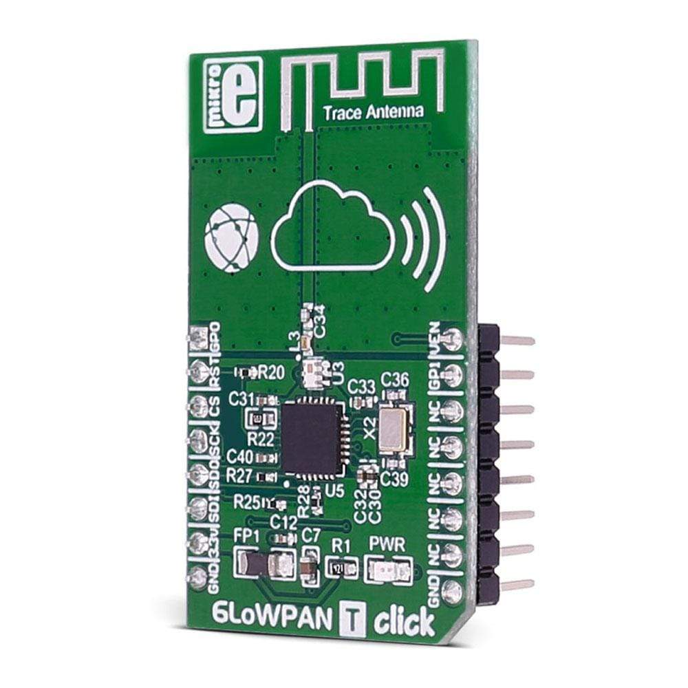
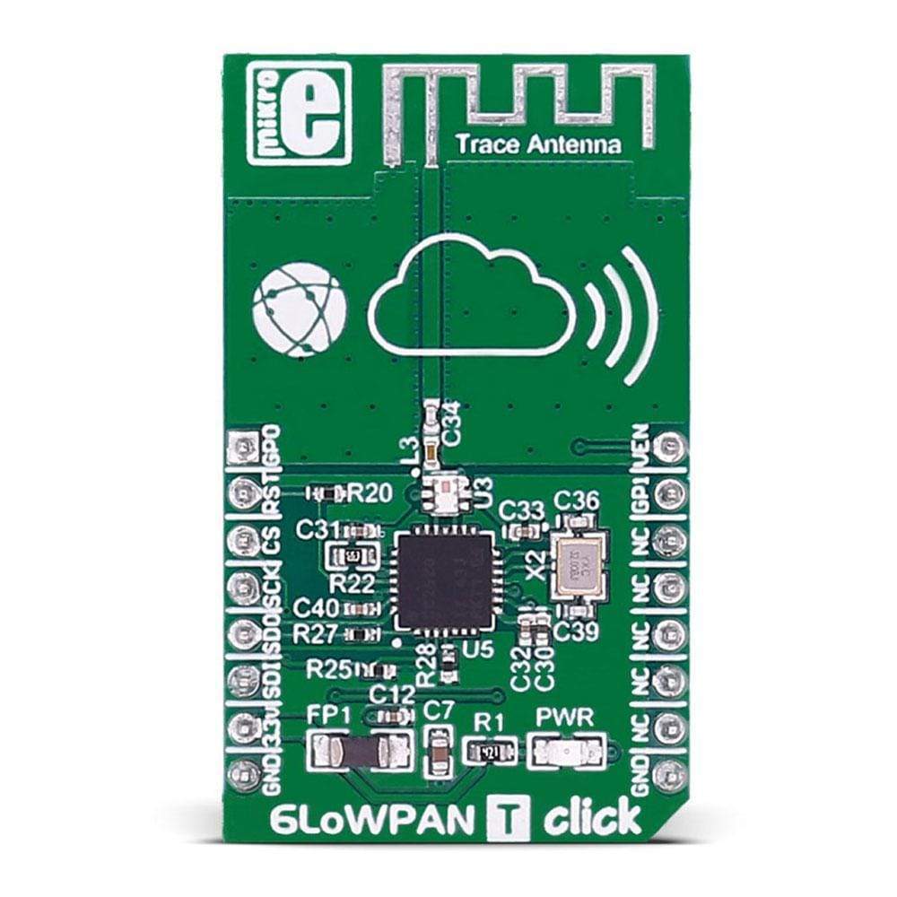
La carte 6LoWPAN T Click Board™ transporte l'émetteur-récepteur RF 2,4 GHz CC2520.
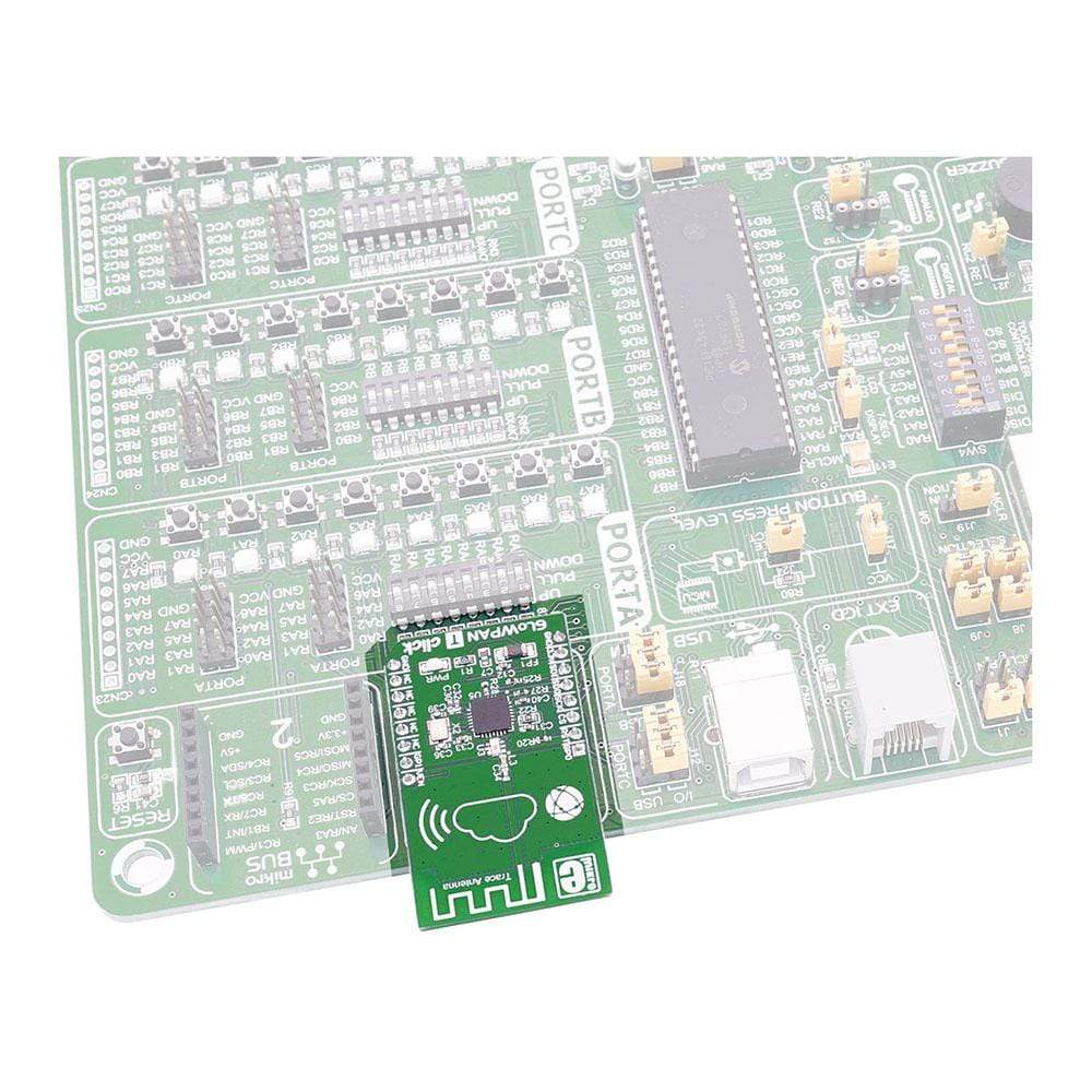
La carte 6LoWPAN T Click Board™ est conçue pour fonctionner sur une alimentation de 3,3 V. Elle communique avec le microcontrôleur cible via l'interface SPI, avec des fonctionnalités supplémentaires fournies par les broches suivantes sur la ligne MikroBUS : PWM, INT, RST, AN.
The 6LoWPAN T Click Board™ is based on the CC2520 2.4GHz RF transceiver. The click is designed to run on a 3.3V power supply. It communicates with the target microcontroller over SPI interface, with additional functionality provided by the following pins on the mikroBUS™ line: PWM, INT, RST, AN.
CC2520 Features
The CC2520 is TI's second-generation ZigBee®/IEEE 802.15.4 RF transceiver for the 2.4GHz unlicensed ISM band. This chip enables industrial grade applications by offering state-of-the-art selectivity/co-existence, excellent link budget, operation up to 125°C and low voltage operation.
In addition, the CC2520 provides extensive hardware support for frame handling, data buffering, burst transmissions, data encryption, data authentication, clear channel assessment, link quality indication and frame timing information.
SPECIFICATIONS
Type | 6LoWPAN |
Applications | IEEE 802.15.4 systems, ZigBee® systems, industrial monitoring and control, home and building automation, Automatic Meter Reading, Low-power wireless sensor networks, etc. |
On-board modules | CC2520 is TI's second-generation ZigBee®/IEEE 802.15.4 RF transceiver |
Key Features | Selectivity/co-existence, excellent link budget, operation up to 125°C and low voltage operation |
Interface | GPIO,SPI |
Compatibility | mikroBUS |
Click board size | M (42.9 x 25.4 mm) |
Input Voltage | 3.3V |
PINOUT DIAGRAM
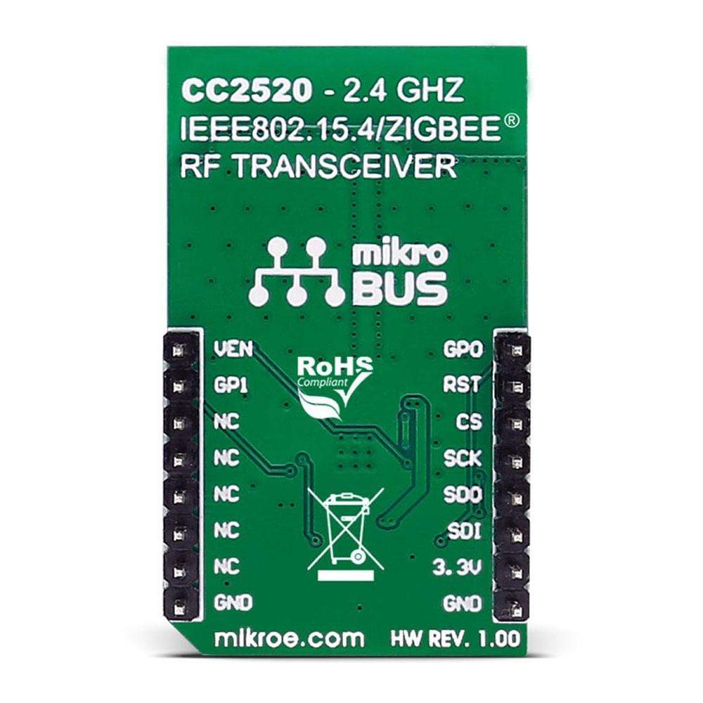
This table shows how the pinout of the 6LoWPAN T Click Board™ corresponds to the pinout on the mikroBUS™ socket (the latter shown in the two middle columns).
Notes | Pin | Pin | Notes | ||||
---|---|---|---|---|---|---|---|
General purpose digital I/O | RF GPIO0 | 1 | AN | PWM | 16 | RF VREG EN | When high, digital voltage regulator is active |
External reset pin, active low | RF RST# | 2 | RST | INT | 15 | RF GPIO 1 | General purpose digital I/O |
Chip select | RF CS | 3 | CS | TX | 14 | NC | |
Serial clock | RF SCK | 4 | SCK | RX | 13 | NC | |
Master input slave output | RF MISO | 5 | MISO | SCL | 12 | NC | |
Master output slave input | RF MOSI | 6 | MOSI | SDA | 11 | NC | |
Power supply | +3.3V | 7 | 3.3V | 5V | 10 | NC | |
Ground | GND | 8 | GND | GND | 9 | GND | Ground |
Software Support
Code examples for the 6LoWPAN T Click Board™, written for MikroElektronika hardware and compilers are available on Libstock.
Note: The full 6LoWPAN stack is not currently implemented in our libraries. However, there are functionalities for sending and receiving data packets, as well as for setting the network ID and 16-bit addresses for individual devices.
CODE SNIPPET
This code snippet, taken from our 6LoWPAN click example for clicker 2 for MSP432, shows how data is transmitted and received between two MCUs using 6LoWPAN clicks.
The value of _RECEIVER_ determines whether the MCU will behave as a receiver or a transmitter. RF channel, PAN ID, and individual addresses are also defined.
There is an interrupt routine for detecting a button press, which is used in the transmitter code to indicate that a package should be sent.
The other interrupt routine is connected to the GP1 line of the click itself and will trigger when new data is ready to be received. It will check the received package, and turn on the data ready indicator if everything is fine.
In the main routine, after some initialization code, two sections can be found - one for the receiver and the other one for the transmitter.
The receiver will check the package ready indicator and handle the received package. In this example, an LED will be toggled to indicate successful data transfer.
The transmitter will wait for a flag to be set from the button interrupt routine. When the flag is set, a package will be sent to the receiver.
01 #if RECEIVER 02 // Initialize BasicRF 03 config.myAddr = LIGHT_ADDR; 04 if (C6LP_init(&config) == FAILED) 05 LED1 = 1; 06 07 C6LP_receiveOn(); 08 EnableInterrupts(); 09 10 while (1) 11 { 12 while (!C6LP_isPacketReady()); 13 14 if (C6LP_receive(pRxData, APP_PAYLOAD_LENGTH, 0) > 0) 15 { 16 if (pRxData[0] == LIGHT_TOGGLE_CMD) 17 { 18 LED0 = !LED0; 19 } 20 } 21 } 22 #else 23 pTxData[0] = LIGHT_TOGGLE_CMD; 24 25 // Initialize BasicRF 26 config.myAddr = SWITCH_ADDR; 27 if (C6LP_init(&config) == FAILED) 28 LED1 = 1; 29 30 // Keep Receiver off when not needed to save power 31 C6LP_receiveOff(); 32 33 flag = 0; 34 EnableInterrupts(); 35 while (1) 36 { 37 if (flag) 38 { 39 flag = 0; 40 LED0 = !LED0; 41 C6LP_sendPacket(LIGHT_ADDR, pTxData, APP_PAYLOAD_LENGTH); 42 EnableInterrupts(); 43 } 44 } 45 #endif
Carte à clic 6LoWPAN T
Frequently Asked Questions
Have a Question?
Be the first to ask a question about this.