

Mikroelektronika d.o.o.
Carte à clic RVB 4X4
Carte à clic RVB 4X4
SKU: MIKROE-1881
Impossible de charger la disponibilité du service de retrait


Overview
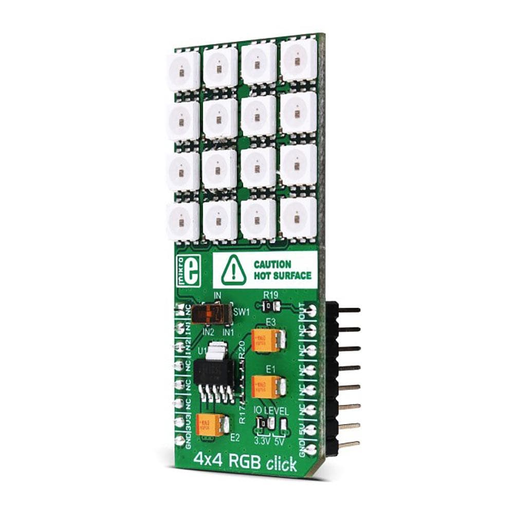
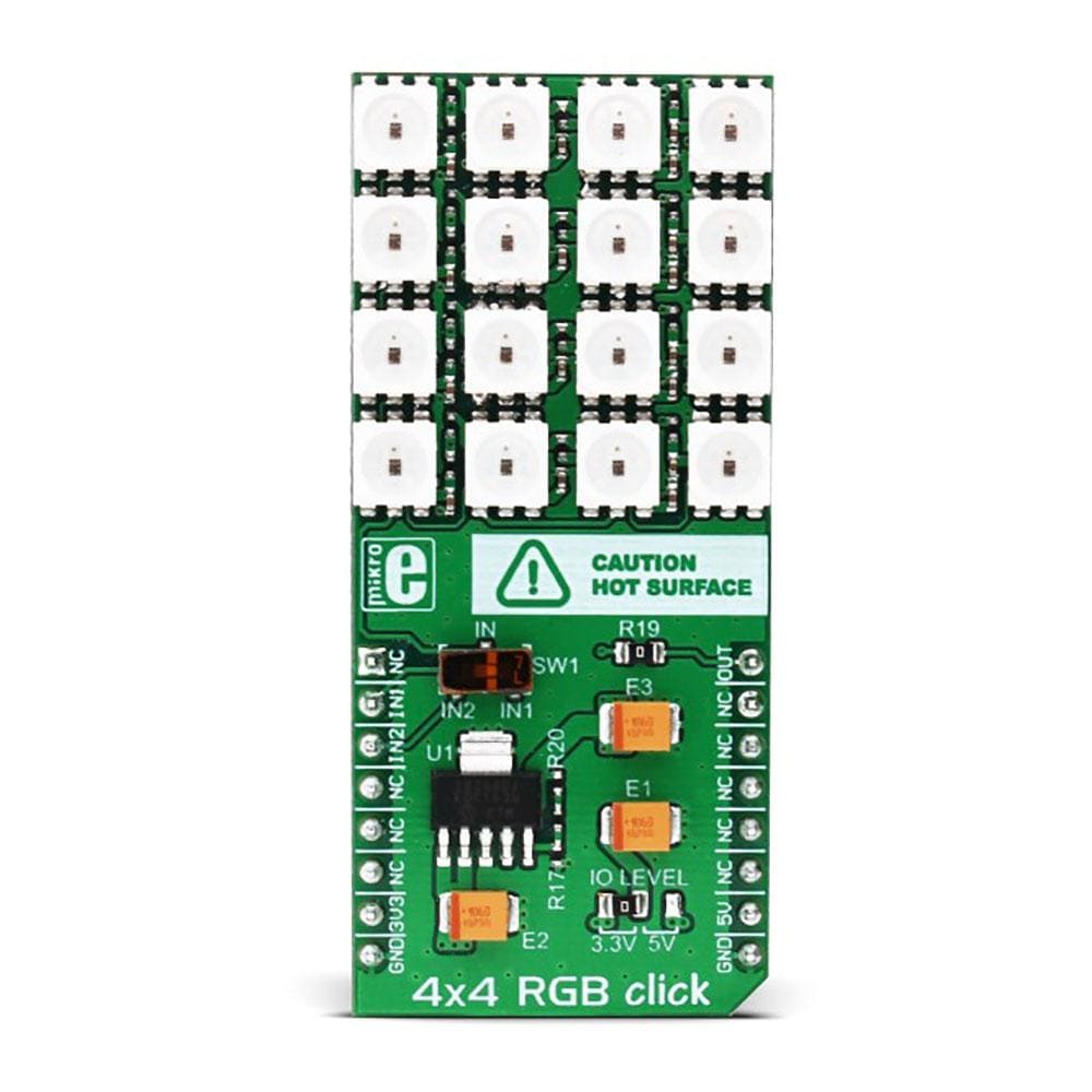
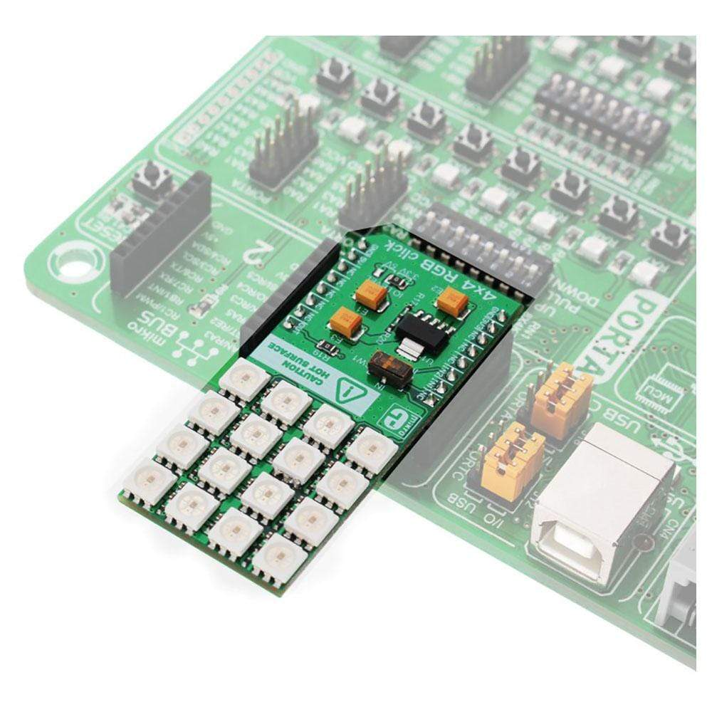
The 4x4 RGB Click Board™ is an add-on board that helps the user to add a colourful RGB LED matrix to the design. This accessory board comes equipped with a matrix of 16 very bright WS2812 RGB LEDs and an MCP1826 low dropout regulator. Each of these 16 LEDs further comprises three single coloured LEDs (Red, Green and Blue), and a control chip. Put together, there are a total of 48 individual LEDs in 4x4 RGB Click Board™. The control circuit and RGB chip have been integrated into a package of 5050 components to keep pixel points in complete control. 4x4 RGB Click Board™ features a jumper (zero Ω resistor) for setting the I/O logic level. It is by default soldered in the 3.3V position but can make use of either a 3.3V or 5V power supply. The LED matrix is connected to the target board microcontroller through the MikroBUS RST pin.
The 4x4 RGB Click Board™ can be used to create animations that can be scrolled on a computer screen. It is also usable for producing spellbinding displays of colourful graphics on electronic billboards, signs, and similar interfaces.
.
Downloads
Le 4x4 RGB Click Board™ est une carte complémentaire qui permet à l'utilisateur d'ajouter une matrice LED RGB colorée à la conception. Cette carte accessoire est équipée d'une matrice de 16 LED RGB WS2812 très lumineuses et d'un régulateur à faible chute de tension MCP1826. Chacune de ces 16 LED comprend en outre trois LED monochromes (rouge, vert et bleu) et une puce de contrôle. Ensemble, il y a un total de 48 LED individuelles dans le 4x4 RGB Click Board™. Le circuit de contrôle et la puce RGB ont été intégrés dans un ensemble de composants 5050 pour garder les points de pixel sous contrôle complet. Le 4x4 RGB Click Board™ dispose d'un cavalier (résistance zéro Ω) pour régler le niveau logique d'E/S. Il est soudé par défaut en position 3,3 V mais peut utiliser une alimentation 3,3 V ou 5 V. La matrice LED est connectée au microcontrôleur de la carte cible via la broche MikroBUS RST.
Le Click Board™ 4x4 RGB peut être utilisé pour créer des animations qui peuvent défiler sur un écran d'ordinateur. Il est également utilisable pour produire des affichages envoûtants de graphiques colorés sur des panneaux d'affichage électroniques, des panneaux et des interfaces similaires.
.
| General Information | |
|---|---|
Part Number (SKU) |
MIKROE-1881
|
Manufacturer |
|
| Physical and Mechanical | |
Weight |
0.034 kg
|
| Other | |
EAN |
8606015076430
|
Frequently Asked Questions
Have a Question?
Be the first to ask a question about this.