


Mikroelektronika d.o.o.
Tableau de clic couleur
Tableau de clic couleur
SKU: MIKROE-1438
Impossible de charger la disponibilité du service de retrait
Overview
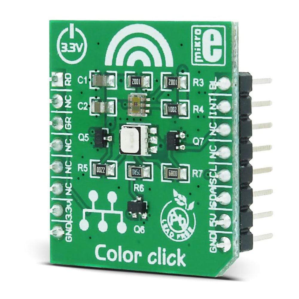
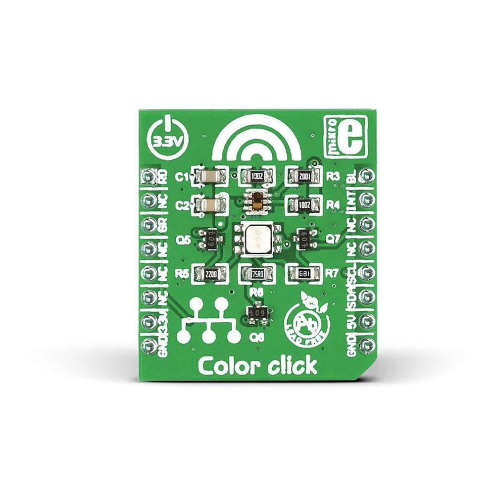
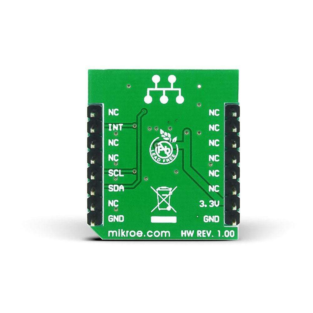
Add colour sensing functionality to your device with the MikroE Color Click Board™. This compact accessory board employs TCS3471 colour light-to-digital converter sensor, three NPN resistor-equipped transistors, as well an RGB LED diode. With a resolution of up to 16 bits, the TCS3471 colour light sensor provides red, green, blue, and clear light sensing (RGBC) that detects light intensity under a variety of lighting conditions and through a variety of attenuation materials. The Color Click Board™ uses the MikroBUS I2C lines (SDA and SCK) to communicate with the target microcontroller and uses 3 digital output lines to drive RGB LED. Featuring a programmable interrupt function, it reduces microprocessor interrupt overhead. The board is designed to use a 3.3V power supply only.
In the absence of any light source, RGB LED provides light for the illumination of objects. The Color Click Board™ is an ideal choice for RGB LED backlight control, a light colour temperature monitor, industrial process control, medical diagnostic equipment, healthcare/medical, and many more.
Downloads
Ajoutez une fonctionnalité de détection de couleur à votre appareil avec la carte MikroE Color Click Board™ . Cette carte accessoire compacte utilise un capteur de conversion de lumière couleur en numérique TCS3471, trois transistors équipés de résistances NPN, ainsi qu'une diode LED RVB. Avec une résolution allant jusqu'à 16 bits, le capteur de lumière couleur TCS3471 fournit une détection de lumière rouge, verte, bleue et claire (RGBC) qui détecte l'intensité lumineuse dans diverses conditions d'éclairage et à travers divers matériaux d'atténuation. La carte Color Click Board™ utilise les lignes MikroBUS I2C (SDA et SCK) pour communiquer avec le microcontrôleur cible et utilise 3 lignes de sortie numériques pour piloter la LED RVB. Dotée d'une fonction d'interruption programmable, elle réduit la surcharge d'interruption du microprocesseur. La carte est conçue pour utiliser uniquement une alimentation 3,3 V.
En l'absence de toute source lumineuse, la LED RVB fournit la lumière nécessaire à l'éclairage des objets. Le Color Click Board™ est un choix idéal pour le contrôle du rétroéclairage LED RVB, un moniteur de température de couleur de lumière, le contrôle des processus industriels, les équipements de diagnostic médical, les soins de santé/médicaux et bien d'autres encore.
| General Information | |
|---|---|
Part Number (SKU) |
MIKROE-1438
|
Manufacturer |
|
| Physical and Mechanical | |
Weight |
0.03 kg
|
| Other | |
EAN |
8606015074658
|
Frequently Asked Questions
Have a Question?
Be the first to ask a question about this.