Carte de clic LCD Mono
Overview
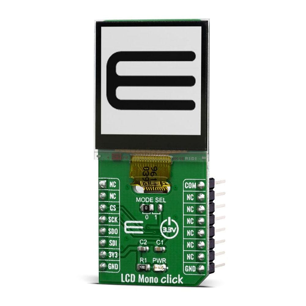
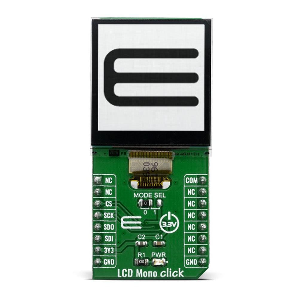
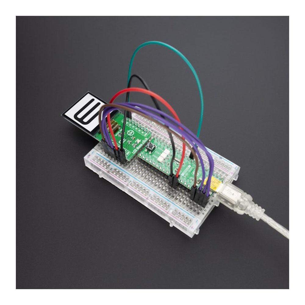
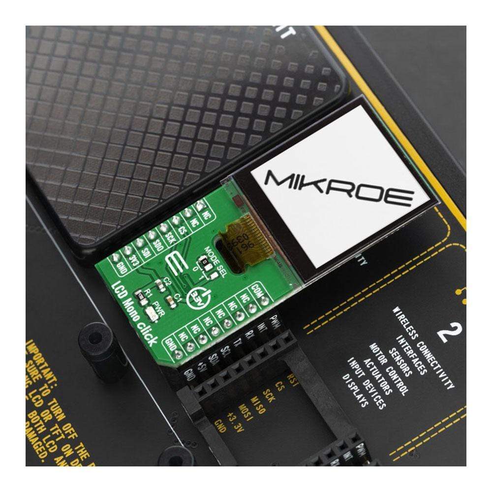
Le LCD Mono Click Board™ utilise l'écran LCD LS013B7DH03 de Sharp qui, combiné à l'EFM32 de Silicon Labs, et à ses capacités d'économie d'énergie, crée une application d'affichage puissante. L'application est capable de piloter un écran de 128 x 128 pixels consommant seulement 2 µA tout en affichant une image statique. Même en mettant à jour le cadre toutes les secondes, la consommation de courant peut être inférieure à 5 µA.
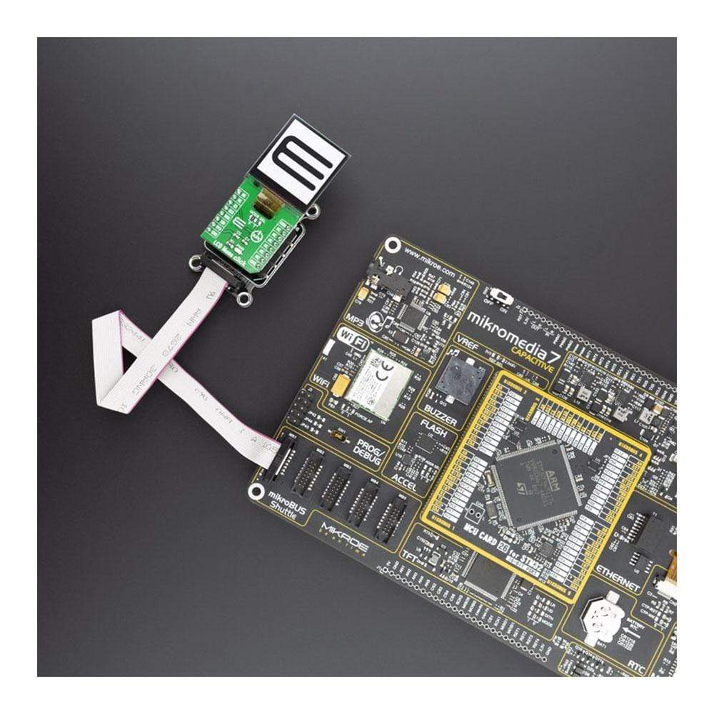
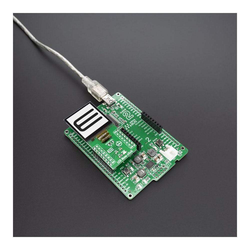
LCD Mono Click est pris en charge par une bibliothèque compatible mikroSDK, qui comprend des fonctions qui simplifient le développement logiciel. Cette Click Board™ est un produit entièrement testé, prêt à être utilisé sur un système équipé du socket mikroBUS™.
How Does The LCD Mono Click Board™ Work?
The LS013B7DH03 LCD display from Sharp has a reflective active-matrix with slightly transmissive type memory liquid crystal display module with 128 x128 panel which uses CG silicon thin film transistor. Its transmissive mode is available by implementation with backlight and you can control the display with serial data signal communication. It features a thin, light and compact module with monolithic technology and its most important feature is the super low power consumption TFT panel. For an MCU application, a powerful display can often be off-limits, either because of price, CPU processing power or power budget. However, if you use the EFM32's energy saving capabilities together with a Sharp low-power matrix memory LCD you can create a powerful display application. The application is capable of driving a 128x128 pixel display drawing as little as 2 µA while showing a static image. Even when updating the frame every second the current consumption can be lower than 5 µA.
The display used for the LCD Mono Click Board™, the LS013B7DH03 LCD, is a 1.28", 128x128 pixels monochrome display, with a 3-wire SPI interface. Apart from the SPI interface, the display requires a 3.3V power supply, and 3 extra pins named EXTMODE, EXTCOMIN and DISP. The SPI protocol consists of three modes. At the start of each SPI transfer, a mode command (1 byte) is sent first. The modes are:
- Update Image
- Toggle Polarity Inversion
- Clear Display
The EXTMODE pin controls how polarity inversion is controlled. The display requires that the polarity across the Liquid Crystal Cell is reversed at a constant frequency. This polarity inversion prevents charge building up within the cell. If EXTMODE is LOW the polarity inversion is toggled by sending a special command over SPI. If it is HIGH polarity inversion is controlled by the EXTCOMIN pin. If EXTMODE is HIGH the polarity inversion is armed for every rising edge of the EXTCOMIN pin. The actual polarity inversion is triggered at the next transision of SCS. The toggling frequency should be at least 1 Hz. If EXTMODE is LOW this pin is ignored. The DISP pin toggles the display on or off (without the pixels losing their state). When LOW the display is off, when HIGH the display is on.
The LCD Mono Click Board™ is designed to be operated only with 3.3V logic level. A proper logic voltage level conversion should be performed before the LCD Mono Click Board™ is used with MCUs with logic levels of 5V.
SPECIFICATIONS
Type | LCD |
Applications | 128x128 pixels monochrome display, with a 3-wire SPI interface |
On-board modules | LS013B7DH03 LCD display from Sharp |
Key Features | EFM32 helps reduce power consumption, driving a 128x128 pixel display drawing as little as 2 µA while showing a static image |
Interface | GPIO,SPI |
Compatibility | mikroBUS |
Click board size | L (57.15 x 25.4 mm) |
Input Voltage | 3.3V |
PINOUT DIAGRAM
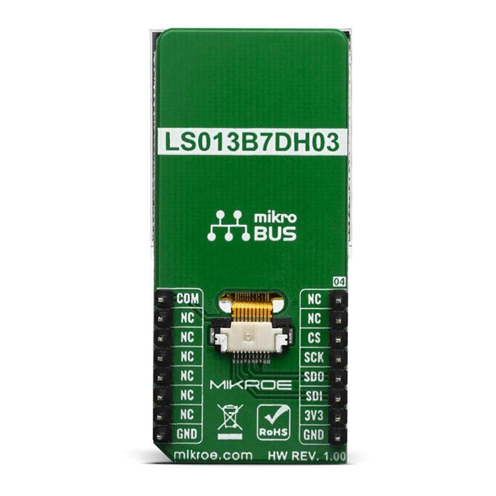
This table shows how the pinout on the LCD Mono Click Board™ corresponds to the pinout on the mikroBUS™ socket (the latter shown in the two middle columns).
Notes | Pin | Pin | Notes | ||||
---|---|---|---|---|---|---|---|
NC | 1 | AN | PWM | 16 | COM | COM Inversion polarity OUT | |
NC | 2 | RST | INT | 15 | NC | ||
Chip Enable | CS | 3 | CS | RX | 14 | NC | |
SPI Clock | SCK | 4 | SCK | TX | 13 | NC | |
SPI Data Out | SDO | 5 | MISO | SCL | 12 | NC | |
SPI Data IN | SDI | 6 | MOSI | SDA | 11 | NC | |
Power Supply | 3.3V | 7 | 3.3V | 5V | 10 | NC | |
Ground | GND | 8 | GND | GND | 9 | GND | Ground |
ONBOARD SETTINGS AND INDICATORS
Label | Name | Default | Description |
---|---|---|---|
LD1 | PWR | - | Power LED indicator |
JP1 | MODE SEL | Left | COM Inversion mode Selection jumper: left position 0, right position 1 |
We provide a library for the LCD Mono Click Board™ on our LibStock page, as well as a demo application (example), developed using MikroElektronika compilers. The demo can run on all the main MikroElektronika development boards.
Library Description
The library initializes and defines the SPI bus driver and drivers that offer a choice for writing data. The library includes function for displays image or frame, draw text on the screen and function for settings font.
Key Functions
void lcdmono_draw_const_frame ( const uint8_t *frame_data )
- Displays draw const framevoid lcdmono_draw_text ( char *text_buf, lcdmono_text_settings_t *cfg , uint8_t end_mode)
- Draw text on the screenvoid lcdmono_set_font ( const uint8_t *font )
- Set fontvoid lcdmono_display_reset ( void )
- Reset procedure
Example Description
The application is composed of three sections :
- System Initialization - Initialization SPI modules and all necessary GPIO pins
- Application Initialization - Driver initialization - Starting LCD Mono display. Print text to the display by changing font size
- Application Task - Drawing an image to the display every 3 second.
void applicationTask ( ) { lcdmono_draw_const_frame( &demo_img_mikroe_light[ 0 ] ); Delay_ms( 3000 ); lcdmono_draw_const_frame( &demo_img_mikroe[ 0 ] ); Delay_ms( 3000 ); lcdmono_draw_const_frame( &demo_img_logo_light[ 0 ] ); Delay_ms( 3000 ); lcdmono_draw_const_frame( &demo_img_logo[ 0 ] ); Delay_ms( 3000 ); }
Create Image: Save the image in resolution of 128x128 px with the extension (monochrome bmp) ... Upload the image to Image2Lcd program Set parameters to:
- Output file type : C array
- Scan Mode : Horisontal scan
- Bits Pixel : monochrome
- Max width and height : 128x128
- Check only MSB first
- Check Reverse color and adjust Normal type
The image to be generated should contain about 2048 bytes ... Insert the image into the file Click_LCD_Mono_image.h
Create Font: Close existing project, open a new VTFT project Add label and adjust text font Generate source code Copy the font from resource.c file to this project in file Click_LCD_Mono_font.h
The full application code, and ready to use projects can be found on our LibStock page.
Other mikroE Libraries used in the example:
- SPI
- UART
Additional notes and informations
Depending on the development board you are using, you may need a USB UART click, USB UART 2 click or RS232 click to connect to your PC, for development systems with no UART to USB interface available on the board. The terminal available in all MikroElektronika compilers, or any other terminal application of your choice, can be used to read the message.
MIKROSDK
The LCD Mono Click Board™ is supported with mikroSDK - MikroElektronika Software Development Kit. To ensure proper operation of mikroSDK compliant Click board™ demo applications, mikroSDK should be downloaded from the LibStock and installed for the compiler you are using.
Frequently Asked Questions
Have a Question?
Be the first to ask a question about this.