Tableau de fréquence cardiaque à 6 clics
Overview
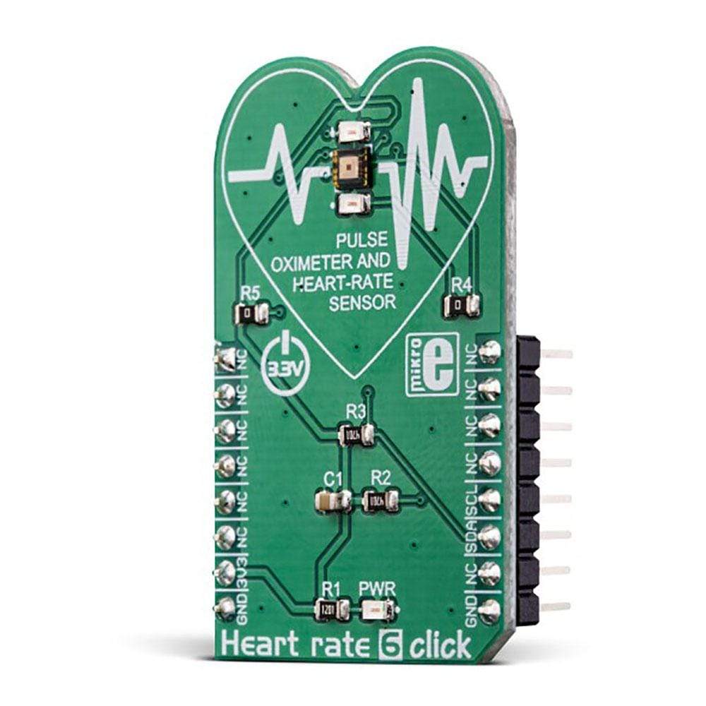
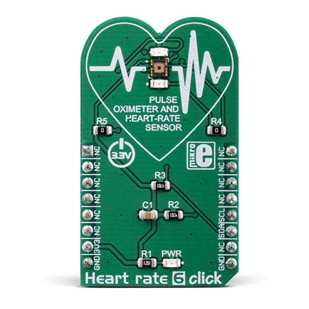
Le Heart Rate 6 Click Board™ est un biocapteur optique Click Board™ conçu pour la surveillance de la fréquence cardiaque (HRM). Ce Click Board™ utilise un capteur spécialisé qui intègre deux pilotes LED et des éléments photo-détecteurs qui sont les plus sensibles à la lumière verte. La lumière verte est le plus souvent utilisée pour mesurer la dilatation des vaisseaux sanguins, c'est pourquoi le Heart Rate 6 Click Board™ est équipé de deux LED vertes, qui sont pilotées par le BH1790GLC, un capteur intégré monolithique pour la surveillance de la fréquence cardiaque.
Le Heart rate 6 Click Board™ est une solution parfaite pour le développement de divers appareils portables liés à la santé, smartphones, tablettes et applications similaires à espace restreint.
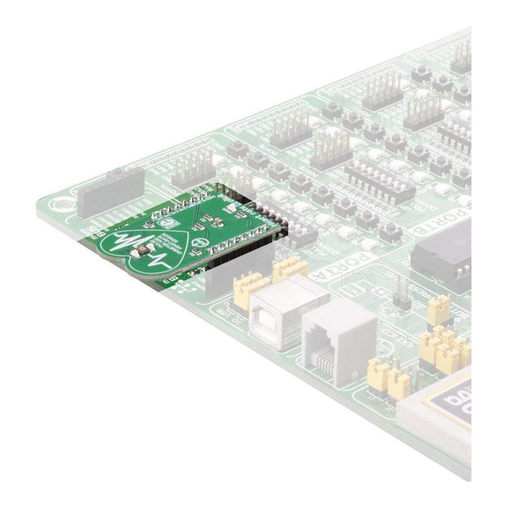
Il est livré dans un package qui comprend également le logiciel mikroSDK et une bibliothèque avec toutes les fonctions. Le Click Board™ est livré sous la forme d'un prototype entièrement testé et approuvé, ce qui en fait un appareil fiable prêt à être utilisé sur la carte de développement.
The photo elements inside the BH1790GLC sensor are located behind the IRCUT filter, which reduces the influence of the IR spectrum of the light. There is a green filter also, narrowing down the green light responsiveness even further, which helps to achieve accurate readings, even by using common green LEDs.
Two LEDs are driven by the BH1790GLC sensor, which provides a constant, programmable current. The choice of LEDs is not critical at all since the integrated light filters on the sensor allow only a narrow band of green light in the range from 520nm to 560nm with 0.8X reduction in respect to the centre frequency (about 540nm). The complete monolithic solution IC with the two constant current LED drivers, narrow pass-band for the green light spectrum, low-power consumption, and a high integration ratio that allows a very low number of external components, make the Heart Rate 6 Click Board™ a perfect solution for development of various wearable health-related devices, smartphones, tablets, and similar space-constrained applications.
Heart Rate Monitoring (HRM)
While the blood passes through the capillary blood vessels, they expand and dilate. Their light reflectance index changes accordingly. This is the basis of the photo-plethysmogram (PPM), a method used for the volumetric measurement of an organ, or in this case - blood vessels. The heart rate signal is calculated according to the changes of the reflected green light, sensed by the PD element. The Heart Rate 6 Click Board™ can provide the HRM readings by simply placing the index finger over the optical sensor.
How Does The Heart Rate 6 Click Board™ Work?
The Heart Rate 6 Click Board™ is equipped with the BH1790GLC, a monolithic integrated sensor for heart rate monitoring, from ROHM Semiconductor company. This IC is a highly integrated optical sensor, very well suited for performing PPM measurements. Due to the large integration scale of this sensor, as well as its low-power consumption, it is perfectly suited to be used on a wearable IoT device. However, being a Click Board™, Heart rate 6 Click Board™ allows easy evaluation and rapid application and firmware development.
Two green LEDs are driven by the integrated LED driving section of the BH1790GLC sensor, with the programmable pulsating frequency of 64Hz or 128Hz. The current through the LEDs can also be programmed in the range from 0 to 60 mA. Finally, there are two settings for the pulse duration: 0.3ms and 0.6ms. These two values affect the duty cycle of the LED pulses. Optimal readings can be achieved by balancing these three parameters: the current amount through the LED (brightness), the speed of the light pulses (LED frequency), and the pulse width (0.3ms or 0.6ms).
The reflected light burst is detected by a sensing element in a form of a photo-diode, sampled by a low noise 16-bit A/D converter. The photo-diode is located behind two light filters which pass only a narrow band of green light in the range from 520nm to 560nm, with 0.8X reduction in respect to the center frequency. The top filter is an IRCUT filter, that prevents the influence of the IR light, while the second filtering layer only passes the green light. This allows even broader color range LEDs to be used, reducing the overall cost of the design. However, Heart rate 6 Click Board™ uses the KingBright super bright clear green LEDs, with the spectral response that is closely matched to the passband properties of the optical filter. This allows most of the LED energy to be used, further improving the power consumption profile.
Two output registers contain the 16-bit measurement in a form of two 8-bit words. The upper and the lower 8-bit registers contain the measurement data, which can be retrieved over the standard I2C interface. The host MCU can read these registers in cycles of 1/32 sec, or 1/64 sec, depending on the BH1790GLC settings. The datasheet of the BH1790GLC contains the correct algorithms, which describe the measurement process with more details. However, the Click Board™ comes with the library which contains functions that allow measurements to be performed with minimum efforts.
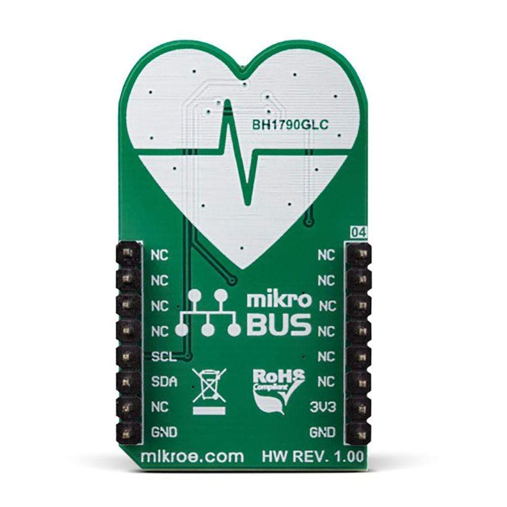
The I2C pins of the BH1790GLC sensor are routed to the respective mikroBUS™ I2C pins. The I2C bus lines are already equipped with two pull-up resistors, which together with the two external LEDs are the only components required by the BH1790GLC sensor. Pullup resistors are connected to the 3.3V power rail so that the Heart Rate 6 Click Board™ can be used only with MCUs that use logic levels up to 3.3V for the communication.
SPECIFICATIONS
Type | Biometrics,Heart Rate |
Applications | This sensor is an ideal solution for development of various wearable health-related devices, smart phones, tablets, and similar space-constrained applications. |
On-board modules | BH1790GLC, a monolithic integrated sensor with I2C interface for heart rate monitoring, from ROHM Semiconductor company |
Key Features | A complete monolithic heart rate measurement solution with two constant current LED drivers, narrow pass-band for the green light spectrum, low power consumption, and a high integration ratio that allows very low number of external components, and more |
Interface | I2C |
Compatibility | mikroBUS |
Click board size | M (42.9 x 25.4 mm) |
Input Voltage | 3.3V |
PINOUT DIAGRAM
This table shows how the pinout on the Heart Rate 6 Click Board™ corresponds to the pinout on the mikroBUS™ socket (the latter shown in the two middle columns).
Notes | Pin | Pin | Notes | ||||
---|---|---|---|---|---|---|---|
NC | 1 | AN | PWM | 16 | NC | ||
NC | 2 | RST | INT | 15 | NC | ||
NC | 3 | CS | RX | 14 | NC | ||
NC | 4 | SCK | TX | 13 | NC | ||
NC | 5 | MISO | SCL | 12 | SCL | I2C Clock | |
NC | 6 | MOSI | SDA | 11 | SDA | I2C Data | |
Power supply | 3V3 | 7 | 3.3V | 5V | 10 | NC | |
Ground | GND | 8 | GND | GND | 9 | GND | Ground |
ONBOARD SETTINGS AND INDICATORS
Label | Name | Default | Description |
---|---|---|---|
PWR | PWR | - | Power LED indicator |
Software Support
We provide a library for the Heart Rate 6 Click Board™ on our LibStock page , as well as a demo application (example), developed using MikroElektronika compilers. The demo can run on all the main MikroElektronika development boards.
Library Description
Library performs the control of the Heart Rate 6 Click Board™ via I2C interface. Library offers a choice to perform a device configuration and a measurement wait time period, and then can read LED Data. For more details check documentation.
Key Functions
void uint8_t heartrate6_writeSingleByte( uint8_t regAddr, uint8_t dataIn )
- Function writes one byte to the register.void uint8_t heartrate6_readBytes( uint8_t startAddr, uint8_t *dataOut, uint8_t nBytes )
- Function reads the desired number of bytes from the registers.
void void heartrate6_getData( uint16_t *ledOffData, uint16_t *ledOnData )
- Function reads the LED Data as 16bit unsigned value.
Example Description
The application is composed of the three sections :
- System Initialization - Initializes peripherals and pins.
- Application Initialization - Initializes I2C interface and performs the device configuration and reset. After that starts measurement.
- Application Task - (code snippet) - Waits until measurement cycle is finished and data is ready for reading. Then reads the LED Data values and performs the data plotting on serial plot, or logging on uart. Note : Uart baud rate should be as high as possible, then data plotting will be more better. I2C clock also should be 100kHz or greater, up to 400kHz, to get better results. The new measurement cycle is started when command for measurement starting is sent, or when register 0x57 is read out. Also the pressure on sensor must be same for the all measurement time, if we want to get the valid results. This is very important to device can work properly.
void applicationTask() { heartrate6_waitMeasure(); heartrate6_getData( &ledDataOFF, &ledDataON ); plotRes( ledDataON ); }
Additional Functions :
void plotRes( uint16_t plotData )
- Performs the data plotting on serial plot.void logRes()
- Performs the data logging on uart.
The full application code, and ready to use projects can be found on our LibStock page.
Other mikroE Libraries used in the example:
Conversions
I2C
UART
Additional Notes and Information
Depending on the development board you are using, you may need a USB UART click, USB UART 2 click or RS232 click to connect to your PC, for development systems with no UART to USB interface available on the board. The terminal available in all MikroElektronika compilers, or any other terminal application of your choice, can be used to read the message.
MIKROSDK
The Heart Rate 6 Click Board™ is supported with mikroSDK - MikroElektronika Software Development Kit. To ensure proper operation of mikroSDK compliant click board demo applications, mikroSDK should be downloaded from the LibStock and installed for the compiler you are using.
Frequently Asked Questions
Have a Question?
Be the first to ask a question about this.