

Mikroelektronika d.o.o.
Tableau à 3 clics Fingerprint
Tableau à 3 clics Fingerprint
SKU: MIKROE-4265
Impossible de charger la disponibilité du service de retrait


Overview
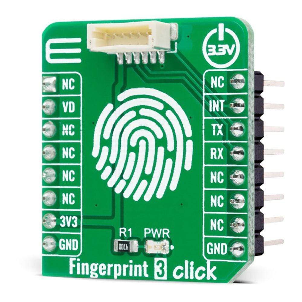
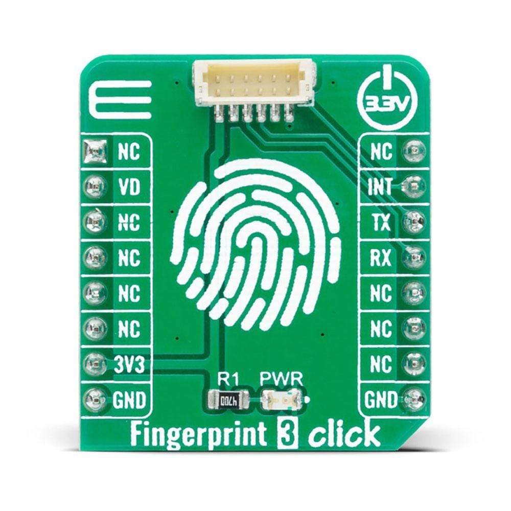
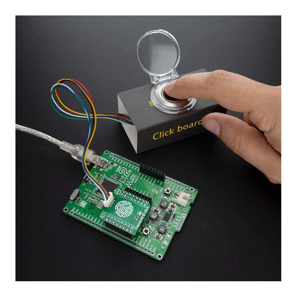
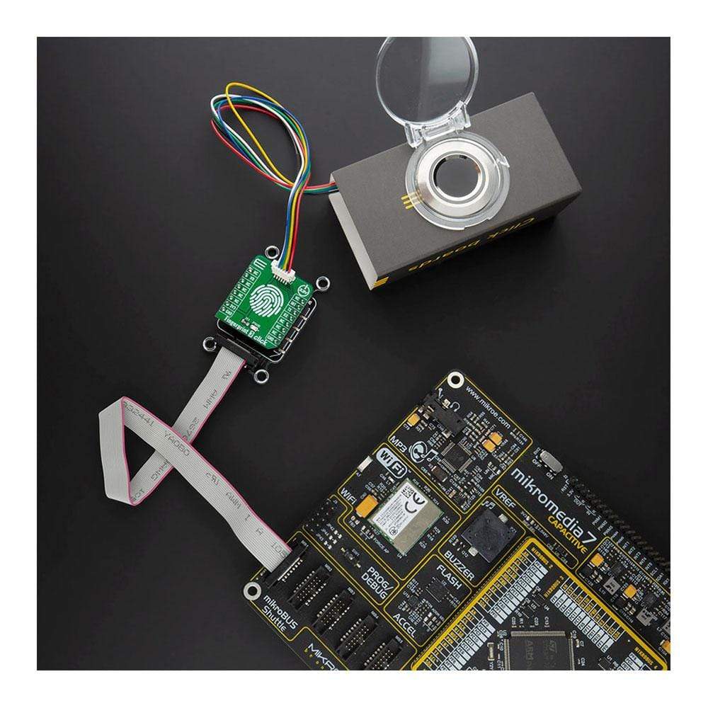
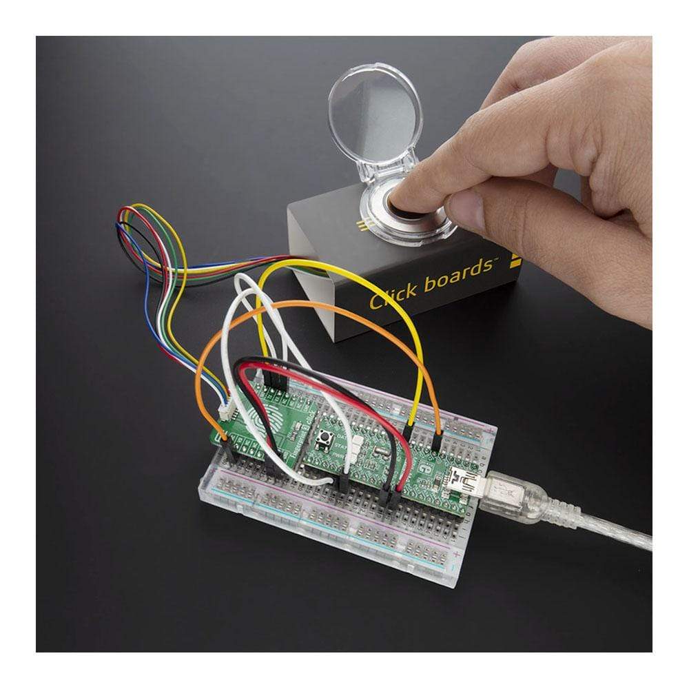
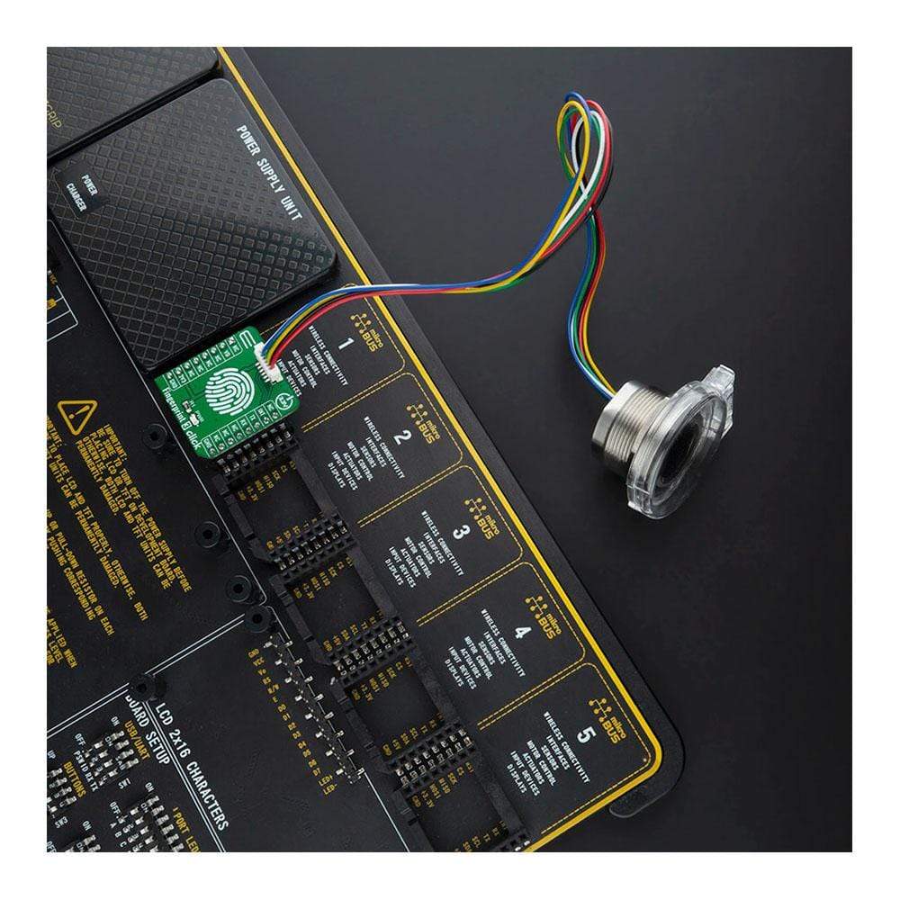
The Fingerprint 3 Click Board™ is an adapter Click Board™, used to interface a compatible Fingerprint Sensor with Two-Color LED Ring with the host MCU. This Click Board™ allows users to secure their projects with a biometric all-in-one fingerprint sensor that will make fingerprint detection and verification super simple. There is a wide range of applications, where Fingerprint 3 Click can be implemented: it can be embedded into a variety of end products such as access control, attendance, or safety deposit box which allows the user to integrate biometric security into its design in the easiest and fastest way.
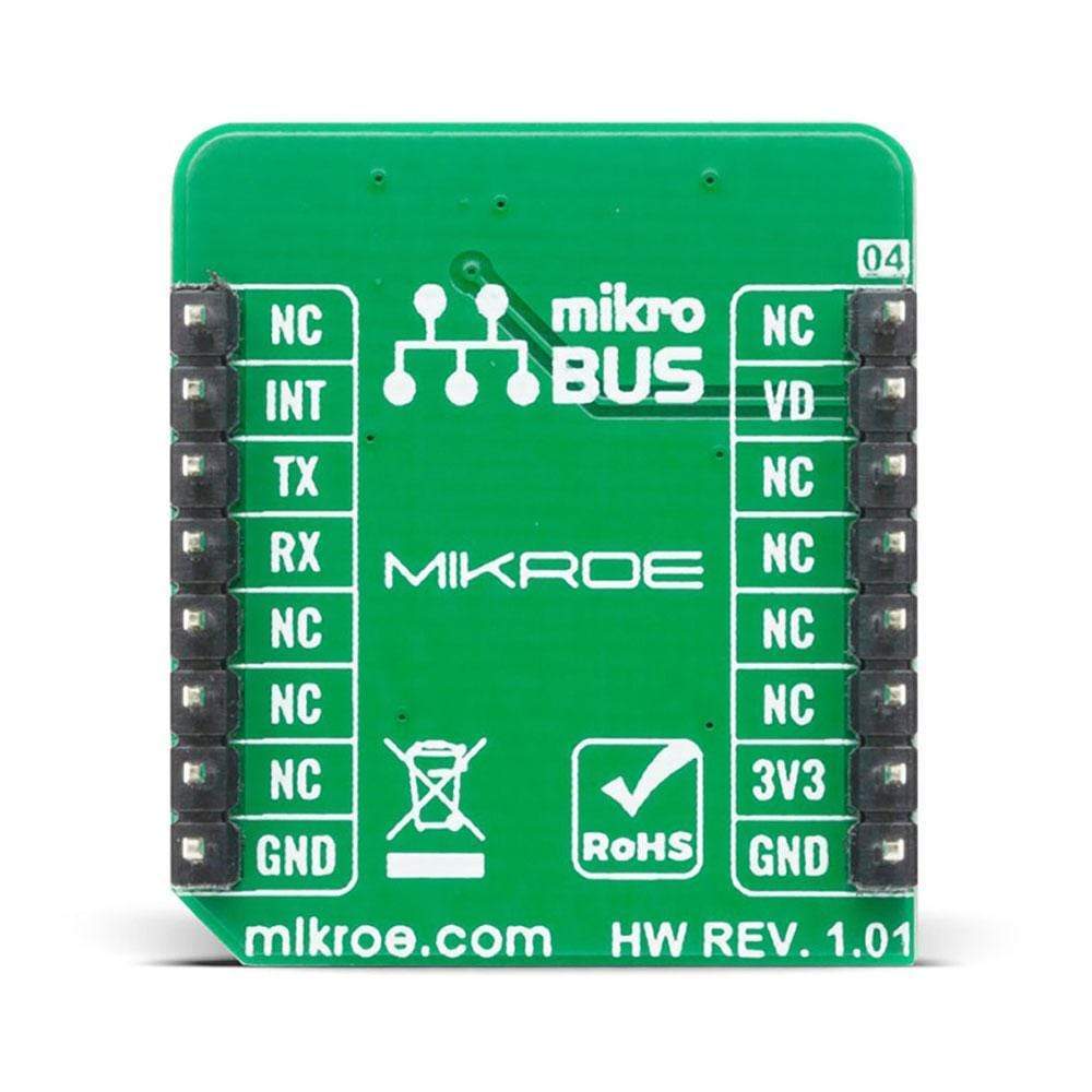
Fingerprint 3 Click is supported by a mikroSDK compliant library, which includes functions that simplify software development. This Click Board™ comes as a fully tested product, ready to be used on a system equipped with the mikroBUS™ socket.
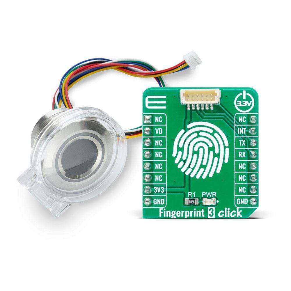
NOTE: The sensor does not come in the same package as this Click Board™. Please visit the Fingerprint 3 Click bundle page for a complete package.
Downloads
Le Fingerprint 3 Click Board™ est un adaptateur Click Board™, utilisé pour connecter un capteur d'empreintes digitales compatible avec anneau LED bicolore au MCU hôte. Ce Click Board™ permet aux utilisateurs de sécuriser leurs projets avec un capteur d'empreintes digitales biométrique tout-en-un qui rendra la détection et la vérification des empreintes digitales extrêmement simples. Il existe une large gamme d'applications dans lesquelles Fingerprint 3 Click peut être mis en œuvre : il peut être intégré dans une variété de produits finis tels que le contrôle d'accès, la présence ou le coffre-fort, ce qui permet à l'utilisateur d'intégrer la sécurité biométrique dans sa conception de la manière la plus simple et la plus rapide.
Fingerprint 3 Click est pris en charge par une bibliothèque compatible mikroSDK, qui comprend des fonctions qui simplifient le développement logiciel. Cette Click Board™ est un produit entièrement testé, prêt à être utilisé sur un système équipé du socket mikroBUS™.
REMARQUE : le capteur n'est pas fourni dans le même emballage que ce Click Board™. Veuillez consulter la page du pack Fingerprint 3 Click pour obtenir un pack complet.
| General Information | |
|---|---|
Part Number (SKU) |
MIKROE-4265
|
Manufacturer |
|
| Physical and Mechanical | |
Weight |
0.016 kg
|
| Other | |
EAN |
8606027380501
|
Frequently Asked Questions
Have a Question?
Be the first to ask a question about this.