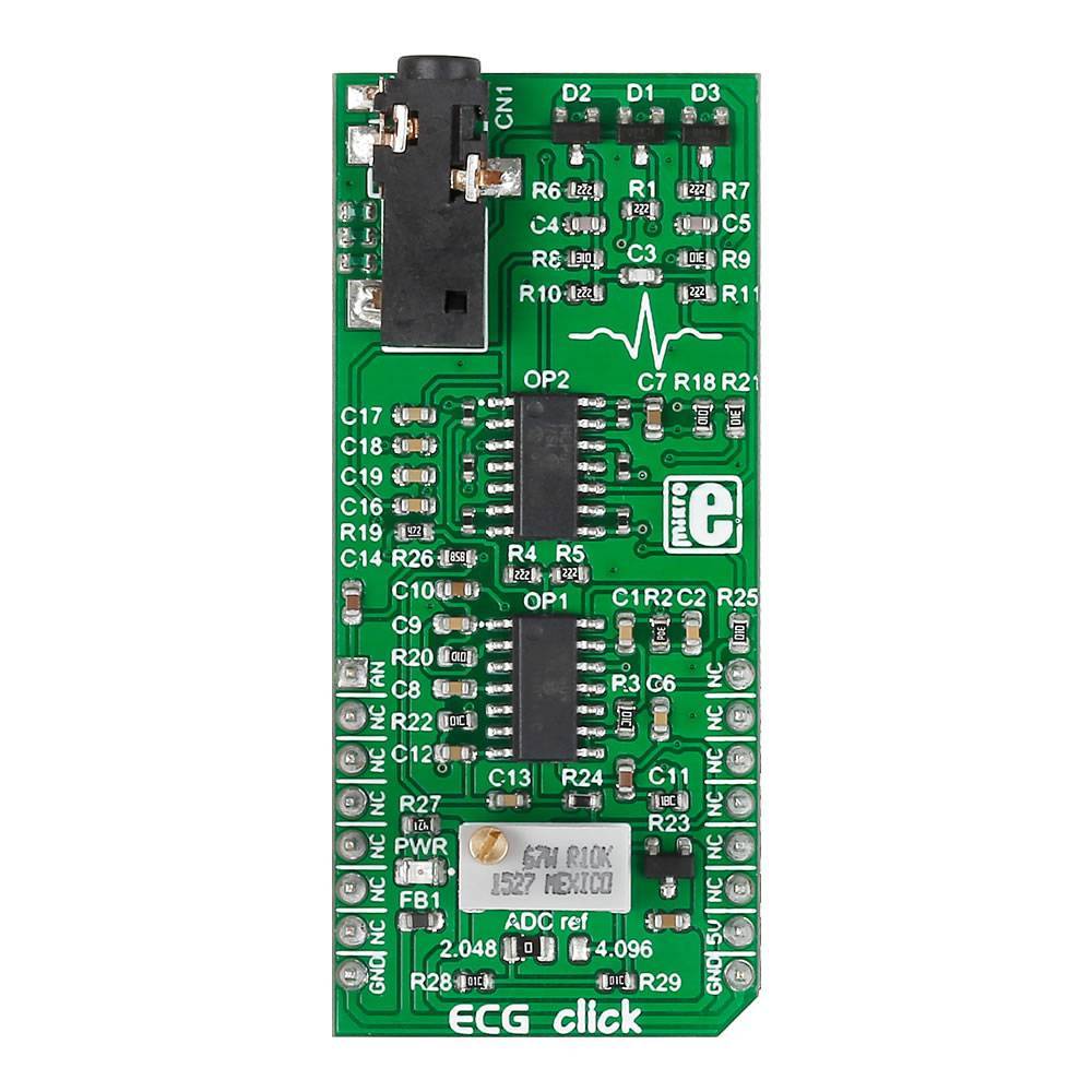
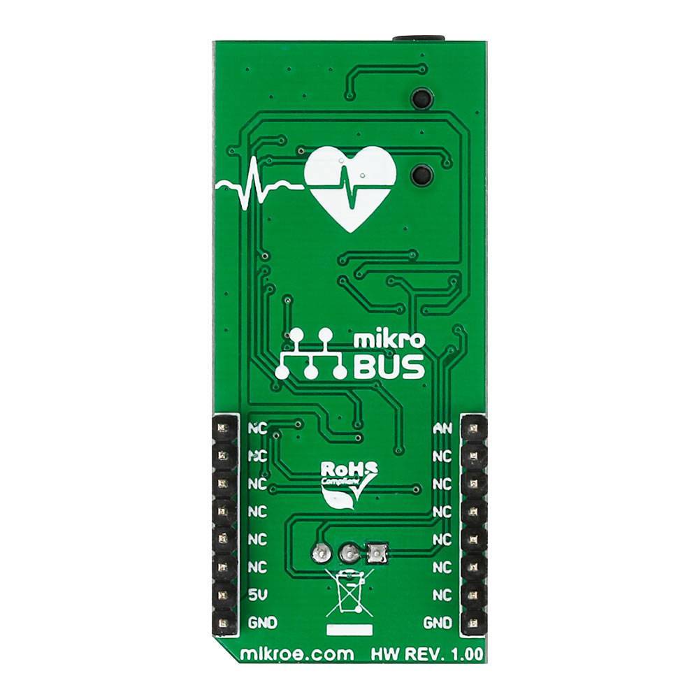
Tableau de clic ECG
Tableau de clic ECG
Overview
L' ECG Click Board™ est un appareil d'ECG (ou EKG) sur un Click Board™. Il mesure l'activité électrique d'un cœur qui bat grâce à des électrodes collées sur la peau. La carte nécessite peu de configuration et les résultats de mesure finaux peuvent être affichés sous forme d'électrocardiogramme à l'aide d'une application Windows gratuite.
How Does The ECG Click Board Work
The ECG Click Board™ is fitted with a 3.5mm jack to which three electrodes are connected. The electrodes will detect the electrical activity of the heart and drive the signal to the 3.5mm jack. After that, the signal needs to be amplified and filtered, therefore the click also contains two amplifiers, two high-pass filters and one low-pass filter.
Once the data is acquired, amplified and filtered, it is sent to one analog pin. The MCU then reads this analog data, converts it to digital, this digital data presents the value of the electrical activity of the heart at that particular moment.
The ECG Click Board™ gathers data from three electrodes, so where do we attach these electrodes? The electrodes have a naming convention, and each has one of these abbreviations: LA, RA, LL - meaning Left Arm, Right Arm, Left Leg. You can already see where this is going, one electrode is placed on the left arm, one on the right arm, and one on the left leg. Usually, though, the LL electrode is not placed on the leg, but right beneath the heart.
Here's a simple illustration:
Electrode placement
Placing the right electrode at the right place is very important, therefore, the cables that come with the click are marked LA, RA and LL, so that our users don't misplace them.
ECG cables
Acquiring the data
Okay, so the click gives us the analog value of the electrical activity of the heart, what now? In order for us to have usable ECG data, we need two parameters: heart data and time.
Yes, time is always an important factor, especially in ECG. A person with 60 heart beats per minute is pretty much okay, but a person with 80 beats per minute has heart problems. Therefore, the MCU will gather ECG data, and also the time when that data is recorded. This way, we will have a time-based overview of the patient's heart beating.
The ECG Click Board™ can be bought along in a bundle with the electrodes and cables which connect them as an ECG Click Board Bundle
ECG bundle
Circuit design: amplifying and filtering the raw signal
By the time it reaches skin surface, the electrical signal from the heart becomes faint. Only few miliVolts. This weak signal is also obstructed by muscle activity from the rest of the body.
Another source of noise is the electromagnetic interference from the environment (the body can act as an antenna).
But the pattern of a beating heart is fairly predictable. This allows us to design circuitry that properly amplifies and filters the electrical signal to get the desired output.
The ECG Click Board™ has a 7 block design. It comprises ESD, overvoltage and overcurrent protection (protecting both the hardware and the person), a pre-amplifier and amplifier, two high-pass filters, a low-pass filter, and a DRL circuit.
Learn more about the hardware design from the docs.mikroe.com page.
Plot your heart beat
MikroPlot is a free data visualization tool (Windows) that can be used to generate an ECG.
The graph is generated from data sent from the MCU (ADC values from ECG click input + time stamp). A UART-USB connection is required.
See the learn.mikroe.com article for more information.
Applications
- Make a portable battery-powered holter with ECG Click Board™, microSD Click Board™ and a Clicker 2 Board
- Quantified-self data logging: subtle variations in your heart-rate occur from second to second. With ECG click you are not limited to the doctor's office. Record ECG while you watch TV, read email, talk over the phone – study patterns to see what excites you (HRV - heart rate variability is a good indicator of state of mind).
- Pair ECG click with a wireless transceiver to transmit a heartbeat signal to various electronics (set a LED strip to pulsate in sync with your heartbeat, or the vibro motor on another person's Hexiwear).
Features
- 7-block design (protection, preamplifier, high-pass filter #1, amplifier, high-pass filter #2, low-pass filter, DRL circuit
- Ready-to-use example and free software tool to generate ECG plot
- Jumpers for setting output voltage range
- Trimmer potentiometer to adjust gain
- MCP609 OpAmp
- MAX6106 Voltage Reference IC
- ESD, OverVoltage and OverCurrent protection
- Analog output (mikroBUS™ AN pin)
- 5V power supply
Software Support
#include #include #include void InitTimer2(){ RCC_APB1ENR.TIM2EN = 1; TIM2_CR1.CEN = 0; TIM2_PSC = 5; TIM2_ARR = 54599; NVIC_IntEnable(IVT_INT_TIM2); TIM2_DIER.UIE = 1; TIM2_CR1.CEN = 1; } static bool read_flag = false; static volatile uint32_t interrupt_ctr = 0; static volatile uint32_t seconds_counter = 0; uint32_t temp_adc_read; double temp_timer_read; void main() { uint16_t adc_read = 0; uint32_t i = 0; char timer_read_string[10]; char final_string [20]; temp_adc_read = temp_timer_read = 0; GPIO_Analog_Input( &GPIOA_BASE, _GPIO_PINMASK_4 ); GPIO_Digital_Input( &GPIOD_BASE, _GPIO_PINMASK_10 ); UART1_Init(57600); delay_ms(500); // Uart1_Write_Text("Uart initialized rn"); // this is for testing only, it should stay commented when implementing ECG reading ADC_Set_Input_Channel(_ADC_CHANNEL_4); ADC1_Init(); Delay_ms(100); while(1) { if (Button(&GPIOD_IDR, 10, 10, 1)) // if the button is pressed, interrupts are activated and the measuring begins { Uart1_Write_Text("STARTrn"); InitTimer2(); EnableInterrupts(); delay_ms(500); } if (read_flag == true) // every 3.9ms, measure data, measure time, and send them to the PC { DisableInterrupts(); temp_adc_read = ADC1_Get_Sample(4); temp_timer_read = interrupt_ctr*3.9; inttostr(temp_adc_read, final_string); sprintf(timer_read_string,"%.2f", temp_timer_read); strcat(final_string, ","); strcat(final_string, timer_read_string); ltrim(final_string); Uart_Write_Text(final_string); Uart_Write_Text("rn"); read_flag = false; EnableInterrupts(); } if (seconds_counter == 15) // after 15 seconds of measuring is done, disable interrupts and finish { DisableInterrupts(); while(1); } } } void Timer2_interrupt() iv IVT_INT_TIM2 { TIM2_SR.UIF = 0; interrupt_ctr++; if (interrupt_ctr % 256 == 0) seconds_counter++; read_flag = true; }
Frequently Asked Questions
Have a Question?
Be the first to ask a question about this.