


Mikroelektronika d.o.o.
Carte double clic EE
Carte double clic EE
SKU: MIKROE-3762
Impossible de charger la disponibilité du service de retrait

Overview
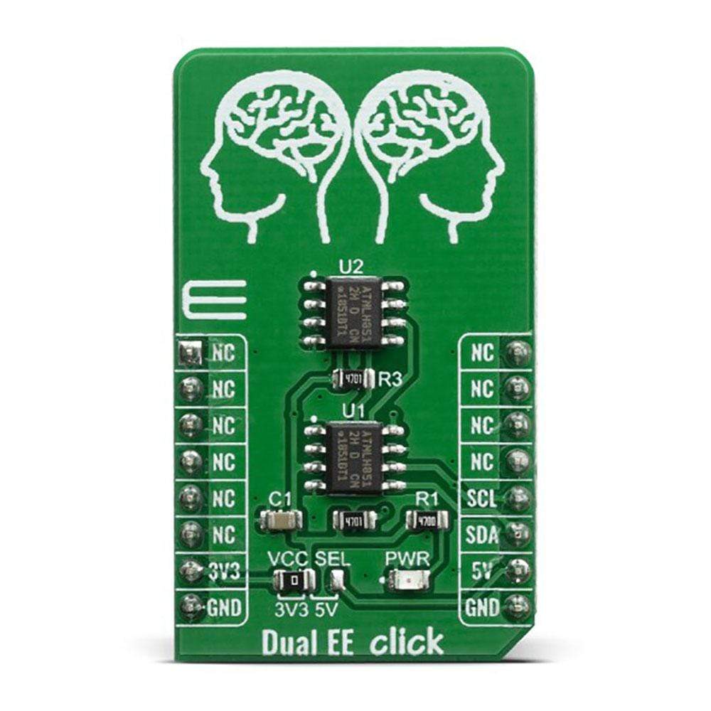
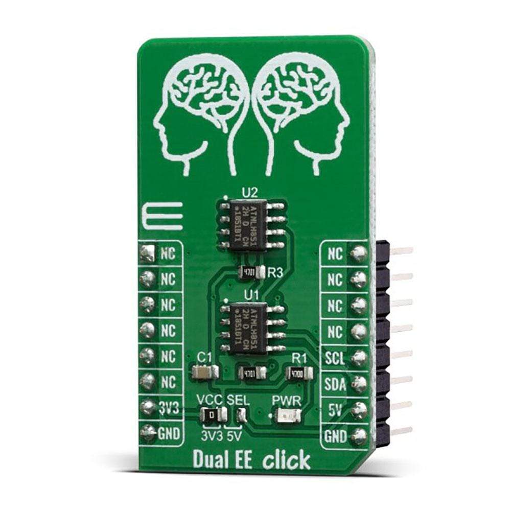
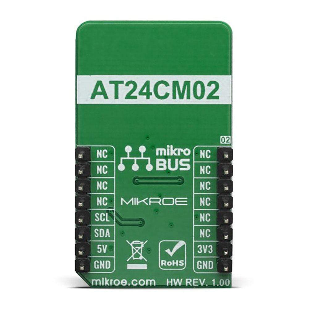
The Dual EE Click Board™ contains two AT24CM02 EEPROM ICs onboard which gives a total of 4MB of memory. Each memory IC can be addressed through the I2C interface with a transfer speed of 400KHz. This Click Board™ offers any kind of temporary or permanent data storage for various. embedded electronic devices, as well as simple data logging or even storing various working parameters of a certain module or device. It can also safeguard all of the sensitive data in case of a particular power cycle and it has many other capabilities.
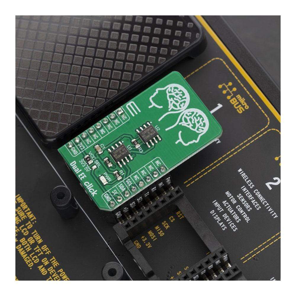
Dual EE Click is supported by a mikroSDK compliant library, which includes functions that simplify software development. This Click Board™ comes as a fully tested product, ready to be used on a system equipped with the mikroBUS™ socket.
Downloads
La carte Dual EE Click Board™ contient deux circuits intégrés EEPROM AT24CM02 intégrés, ce qui donne un total de 4 Mo de mémoire. Chaque circuit intégré de mémoire peut être adressé via l'interface I2C avec une vitesse de transfert de 400 kHz. Cette carte Click Board™ offre tout type de stockage de données temporaire ou permanent pour divers appareils électroniques intégrés, ainsi qu'un enregistrement simple des données ou même le stockage de divers paramètres de fonctionnement d'un certain module ou appareil. Elle peut également protéger toutes les données sensibles en cas de cycle d'alimentation particulier et dispose de nombreuses autres capacités.
Dual EE Click est pris en charge par une bibliothèque compatible mikroSDK, qui comprend des fonctions qui simplifient le développement logiciel. Cette Click Board™ est un produit entièrement testé, prêt à être utilisé sur un système équipé du socket mikroBUS™.
| General Information | |
|---|---|
Part Number (SKU) |
MIKROE-3762
|
Manufacturer |
|
| Physical and Mechanical | |
Weight |
0.018 kg
|
| Other | |
EAN |
8606018716982
|
Frequently Asked Questions
Have a Question?
Be the first to ask a question about this.