


Mikroelektronika d.o.o.
Planche à clic Buck 14
Planche à clic Buck 14
SKU: MIKROE-3847
Impossible de charger la disponibilité du service de retrait


Overview
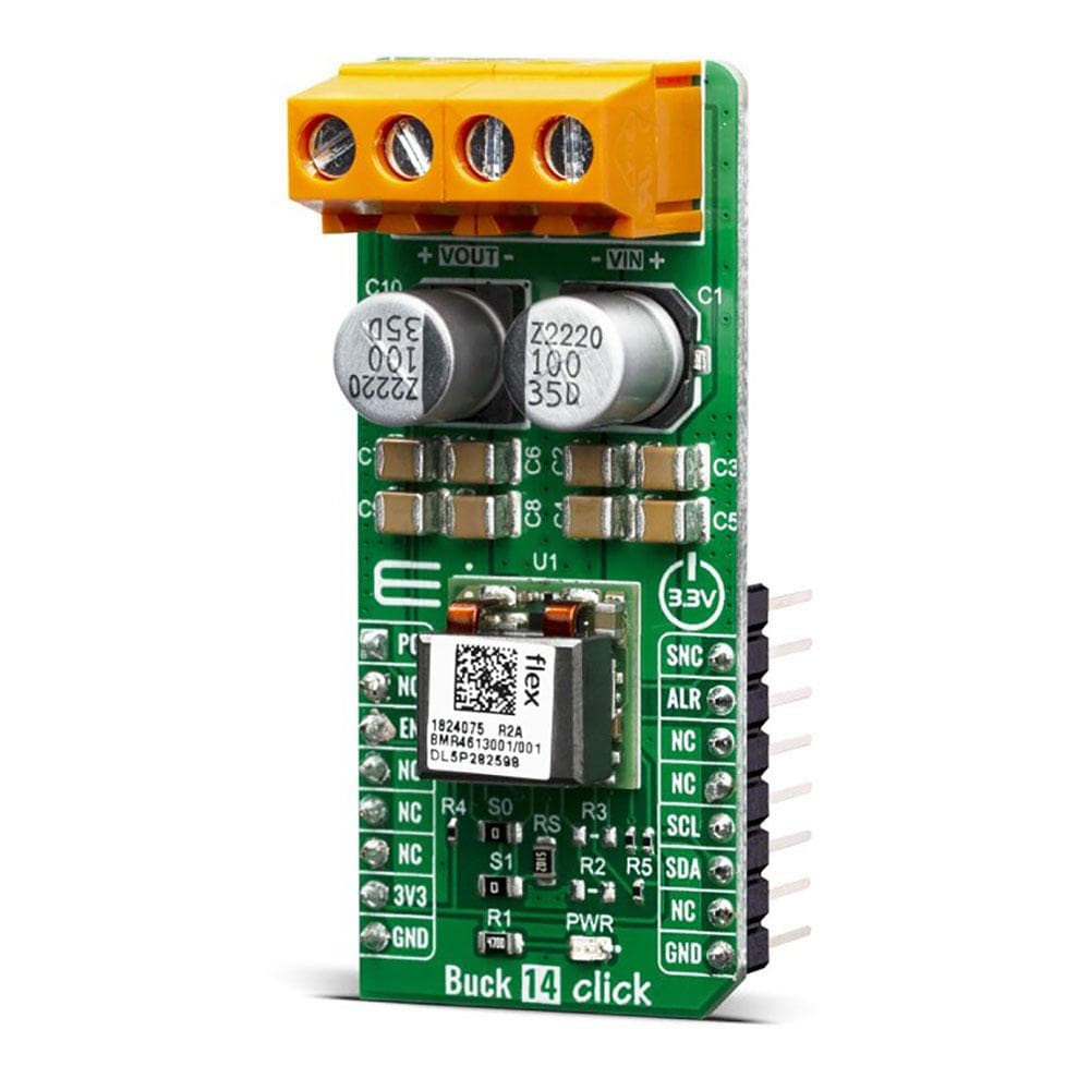
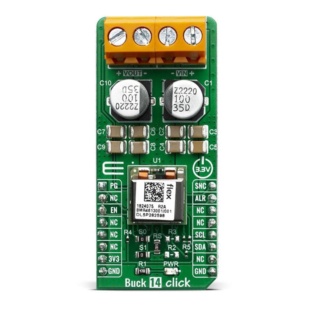
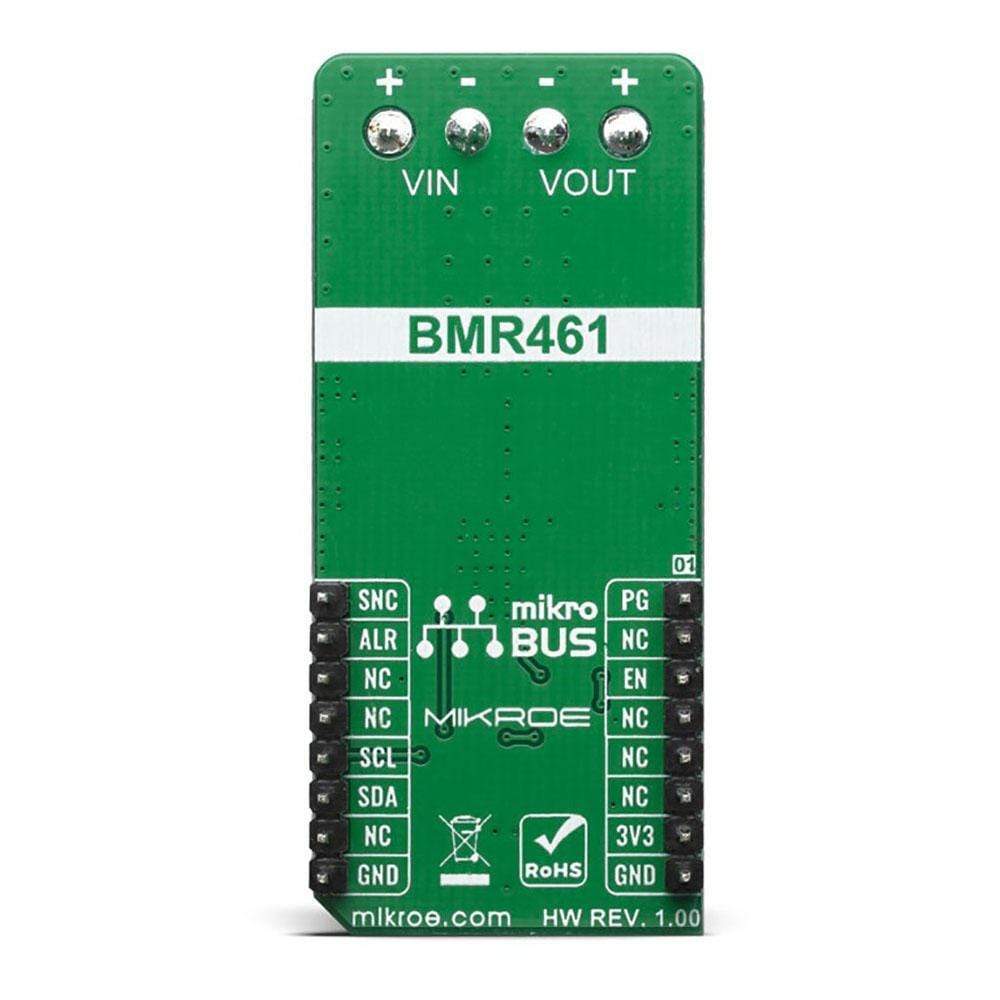
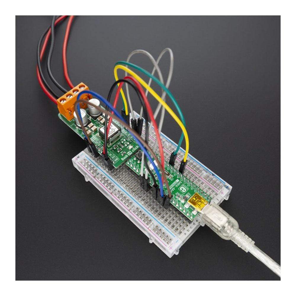
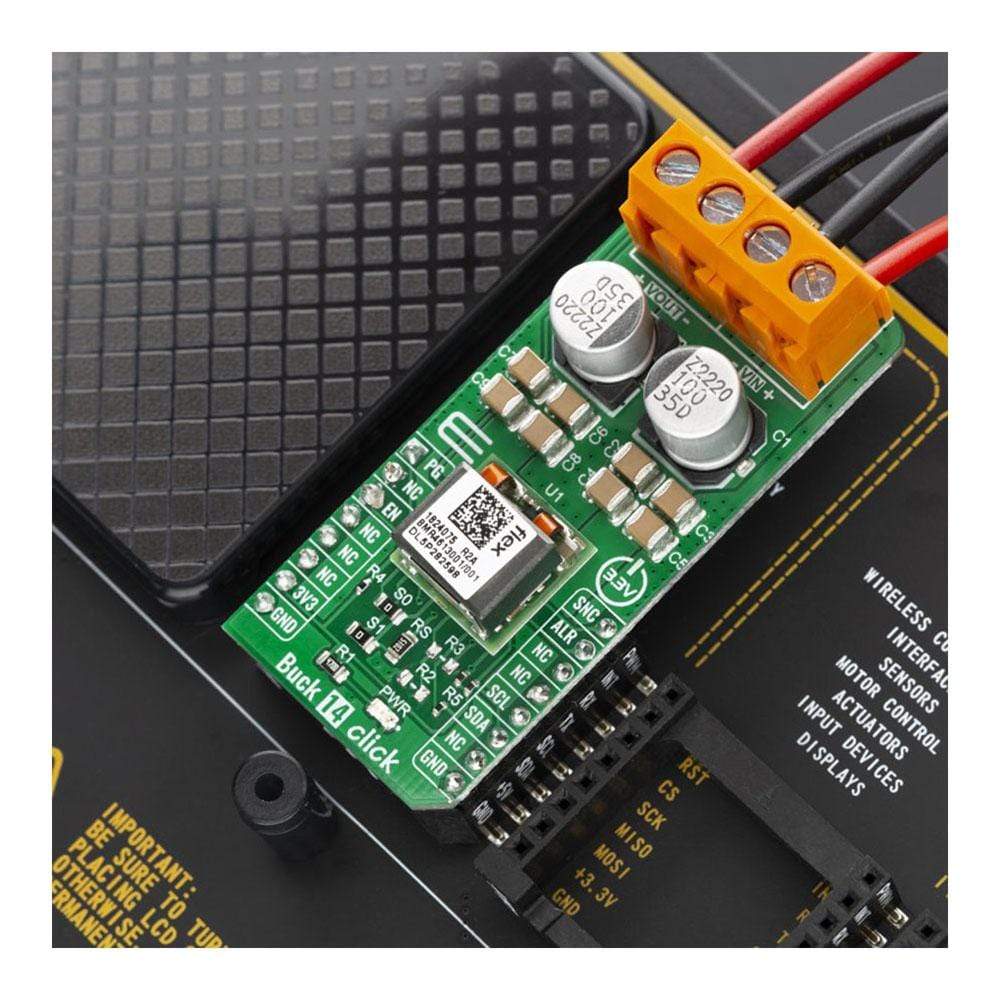
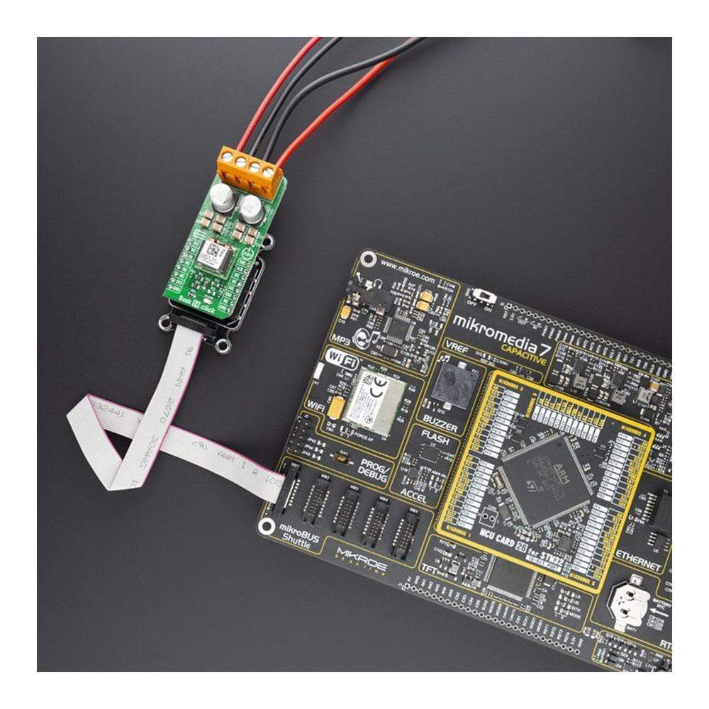
The Buck 14 Click Board™ is based around the BMR4613001/001, a PoL regulator from Flex. It's a high-efficiency step-down converter that provides a highly regulated output voltage derived from the connected power source, rated from 4.5 to 14V. The regulated output voltage can be selected between 0.6V and 5V.
The Buck 14 Click Board™, due to the high efficiency of BMR4613001/001 allows the Click Board™ to easily deliver up to 12A of current with a maximum of 60W of power and high efficiency, typically 96 % at 12Vin, 5Vout and 80% load.
Downloads
Le Buck 14 Click Board™ est basé sur le BMR4613001/001, un régulateur PoL de Flex. Il s'agit d'un convertisseur abaisseur à haut rendement qui fournit une tension de sortie hautement régulée dérivée de la source d'alimentation connectée, évaluée de 4,5 à 14 V. La tension de sortie régulée peut être sélectionnée entre 0,6 V et 5 V.
Le Buck 14 Click Board™, grâce au rendement élevé du BMR4613001/001, permet au Click Board™ de fournir facilement jusqu'à 12 A de courant avec un maximum de 60 W de puissance et un rendement élevé, généralement 96 % à 12 V en entrée, 5 V en sortie et 80 % de charge.
| General Information | |
|---|---|
Part Number (SKU) |
MIKROE-3847
|
Manufacturer |
|
| Physical and Mechanical | |
Weight |
0.02 kg
|
| Other | |
EAN |
8606018719525
|
Frequently Asked Questions
Have a Question?
Be the first to ask a question about this.