Carte Brushless 6 Click
Overview
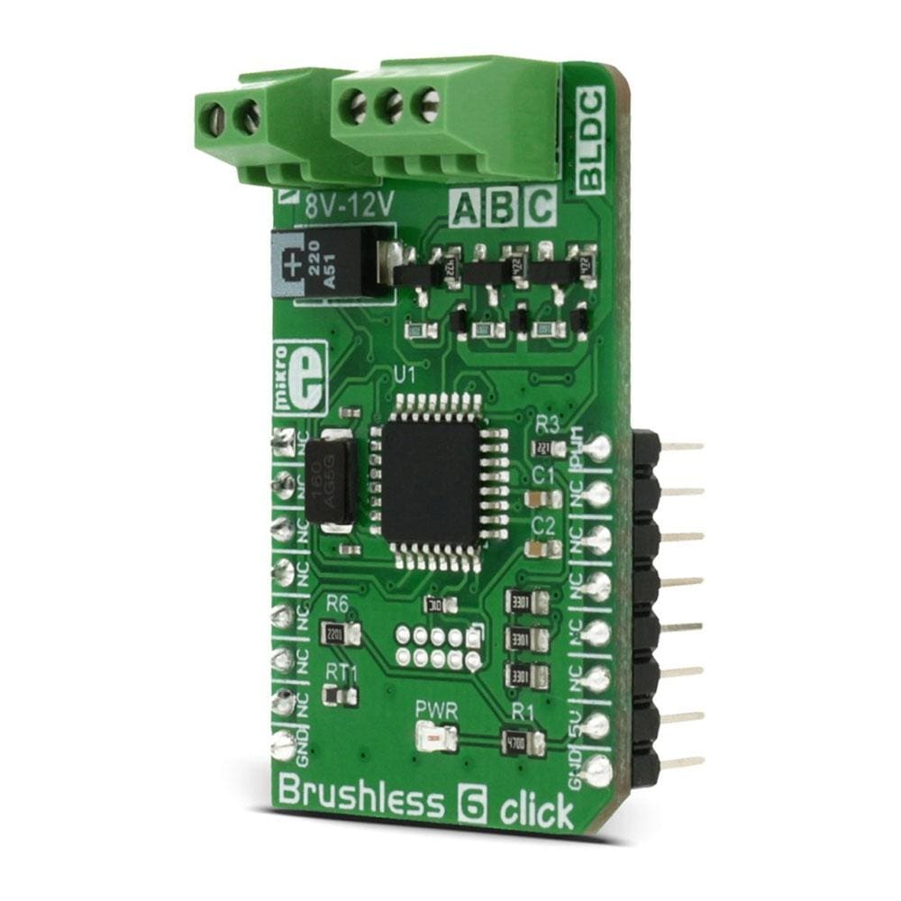
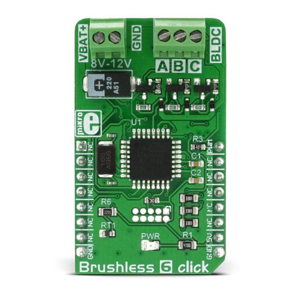
Le Brushless 6 Click Board™ est conçu pour piloter un moteur triphasé sans capteur et sans balai, également connu sous le nom de moteur BLDC. La rotation du moteur est contrôlée par la réception de commandes de pilotage via le signal PWM entrant. Ce Click Board™ contrôle entièrement la rotation du moteur BLDC en utilisant le MCU embarqué ATmega8A, un MCU 8 bits de Microchip. Les sorties du MCU embarqué ne sont pas suffisantes pour alimenter directement les bobines du moteur BLDC, ce MCU est donc utilisé pour contrôler le circuit d'alimentation. Ce circuit se compose de 6 transistors MOSFET, utilisés pour commuter l'alimentation d'une source d'alimentation externe vers les bobines de stator appropriées.
The Brushless 6 Click Board™ is designed to drive a three-phase sensorless, brushless motor, also known as the BLDC motor. The motor rotation is controlled by receiving driving commands via the incoming PWM signal. This click board fully controls the rotation of the BLDC motor by utilizing the onboard MCU ATmega8A, an 8-bit MCU from Microchip. The onboard MCU outputs are not adequate to power on the coils of the BLDC motor directly, so this MCU is used to control the power circuitry, instead. This circuit consists of 6 MOSFET transistors, used to switch the power from an external power source to the appropriate stator coils.
The advantages of the BLDC motors over the other types of DC motors are many. Thanks to their contactless design, BLDC motors last longer and because of the superior rotational speed and torque properties, BLDC motors are widely used for high-speed, lightweight applications such as the drive motors for drones, electronic cooling equipment, small house appliances, robotics and similar applications. The Brushless 6 click provides an easy and elegant solution for driving BLDC motors.
How Does The Brushless 6 Click Board™ Work?
DC brushless motors, also known as BLDC motors, are becoming very popular recently, due to the fact that they have many advantages over some other types of DC motors. The term "brushless" actually means that the rotor of the BLDC motor doesn't have any surfaces which make the electrical contact with the stator because the rotor uses only permanent magnetic materials.
The main control logic component of the Brushless 6 Click Board™ is the ATmega8A MCU from Microchip. It uses a 50Hz PWM signal at one of the input pins, routed to the PWM pin of the mikroBUS™ socket. The duty cycle of the incoming PWM signal is decoded by the onboard ATmega8A MCU so that a certain pulse width range is used to set speed and direction of the rotation. The information about how to properly decode the controller PWM signal can be found in the PWM signal control table, below. MikroElektronika demo application provided with the Brushless 6 click board, uses simplified functions to calibrate and set the speed and the direction of the BLDC motor, so it can be used as the reference for the future design.
Since the MCU output can't be used to drive heavier loads directly, the stator coils are driven through the MOSFET transistors network, controlled by the MCU. The electrical circuit that powers the coils is also known as the "invertor" circuit because it provides both positive and negative voltages from the connected external power supply. The motor can be connected via the onboard connector, which provides an easy and secure connection. There is also a power connector, used to connect the external power supply, up to 12V.
SPECIFICATIONS
Type | Brushless |
Applications | The Brushless 6 Click Board™ can be used to drive BLDC motors for a wide range of applications, such as the BLDC motors for drones, electronic cooling equipment, small home appliances, toys... |
On-board modules | ATmega8A, an 8-bit MCU from Microchip. |
Key Features | Complete driving and control of the BLDC sensorless motors in both directions. Easy to use PWM signal control through one wire. |
Interface | PWM |
Compatibility | mikroBUS |
Click board size | M (42.9 x 25.4 mm) |
Input Voltage | 5V |
PINOUT DIAGRAM
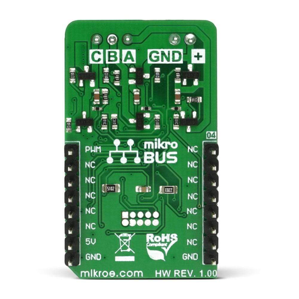
This table shows how the pinout on the Brushless 6 Click Board™ corresponds to the pinout on the mikroBUS™ socket (the latter shown in the two middle columns).
Notes | Pin | Pin | Notes | ||||
---|---|---|---|---|---|---|---|
NC | 1 | AN | PWM | 16 | PWM | PWM control | |
NC | 2 | RST | INT | 15 | NC | ||
NC | 3 | CS | RX | 14 | NC | ||
NC | 4 | SCK | TX | 13 | NC | ||
NC | 5 | MISO | SCL | 12 | NC | ||
NC | 6 | MOSI | SDA | 11 | NC | ||
NC | 7 | 3.3V | 5V | 10 | +5V | Power Supply | |
Ground | GND | 8 | GND | GND | 9 | GND | Ground |
BRUSHLESS 6 CLICK ELECTRICAL SPECIFICATIONS
Description | Min | Typ | Max | Unit |
---|---|---|---|---|
External input voltage range | 8 | 12 | 12 | V |
Output current | 1 | A |
ONBOARD SETTINGS AND INDICATORS
Label | Name | Default | Description |
---|---|---|---|
PWR | Power LED | - | Power LED indicator |
CON1 | Connector | - | External power supply connector |
CON2 | Connector | - | BLDC motor connector |
PWM SIGNAL CONTROL
PWM duty cycle (f = 50Hz) | Command |
---|---|
1ms - 1.5ms | CCW speed (max speed to 0, counterclockwise) |
1.5ms | No rotation |
1.5ms - 2ms | CW speed (0 to max speed, clockwise) |
Note: There is a "dead zone" area around the pulse width of 1.5mS, to compensate for the accuracy of the used controller stick or some other similar control device.
age.
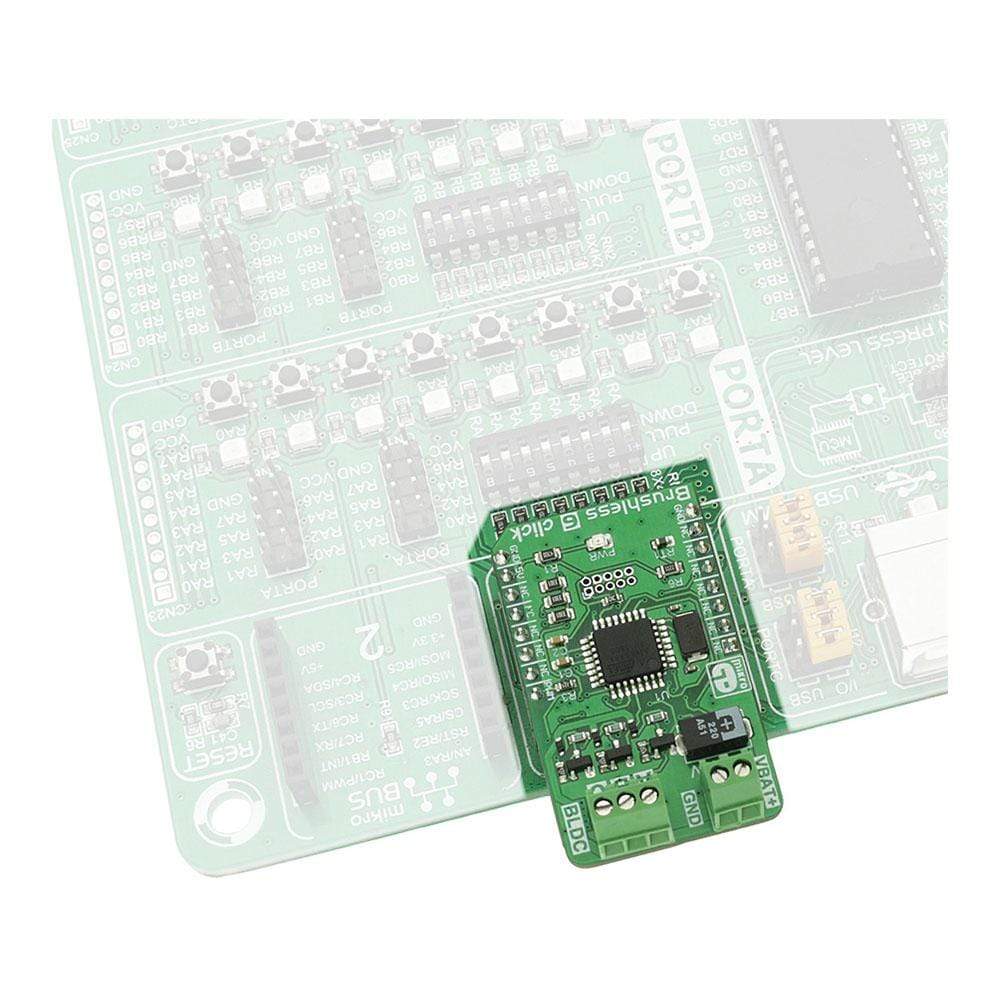
We provide a demo application for the Brushless 6 Click Board™ on our LibStock page, as well as a demo application (example), developed using MikroElektronika compilers. The demo can run on all the main MikroElektronika development boards.
Example Description
The example demonstrates how to initialize and control a brushless motor using Brushless 6 click. The demo application is composed of two sections :
- systemInit - Initializes PWM module but also and Brushless click by executing initialization procedure. Initialized UART module is used for message logging.
- appTask - Periodically changes the motor speed using PWM module but also log current setting to UART.
void applicationTask() { brushless6_setMotor( _BRUSHLESS6_SPEED1 ); UART_Write_Text( " Speed 1 "); UART_Write( 13 ); UART_Write( 10 ); Delay_ms( 1000 ); brushless6_setMotor( _BRUSHLESS6_SPEED2 ); UART_Write_Text( " Speed 2 "); UART_Write( 13 ); UART_Write( 10 ); Delay_ms( 1000 ); brushless6_setMotor( _BRUSHLESS6_SPEED3 ); UART_Write_Text( " Speed 3 "); UART_Write( 13 ); UART_Write( 10 ); Delay_ms( 1000 ); brushless6_setMotor( _BRUSHLESS6_CCW ); UART_Write_Text( " Direction Change "); UART_Write( 13 ); UART_Write( 10 ); Delay_ms( 1000 ); brushless6_setMotor( _BRUSHLESS6_INIT ); UART_Write_Text( " Stoped "); UART_Write( 13 ); UART_Write( 10 ); Delay_ms( 1000 ); }
The full application code, and ready to use projects can be found on our LibStock page.
Other MikroElektronika libraries used in the example:
- PWM
- UART
Additional Notes and Information
Depending on the development board you are using, you may need a USB UART click, USB UART 2 click or RS232 click to connect to your PC, for development systems with no UART to USB interface available on the board. The terminal available in all MikroElektronika compilers, or any other terminal application of your choice, can be used to read the mess
Frequently Asked Questions
Have a Question?
Be the first to ask a question about this.