Carte à clic BLE 2
Carte à clic BLE 2
Overview
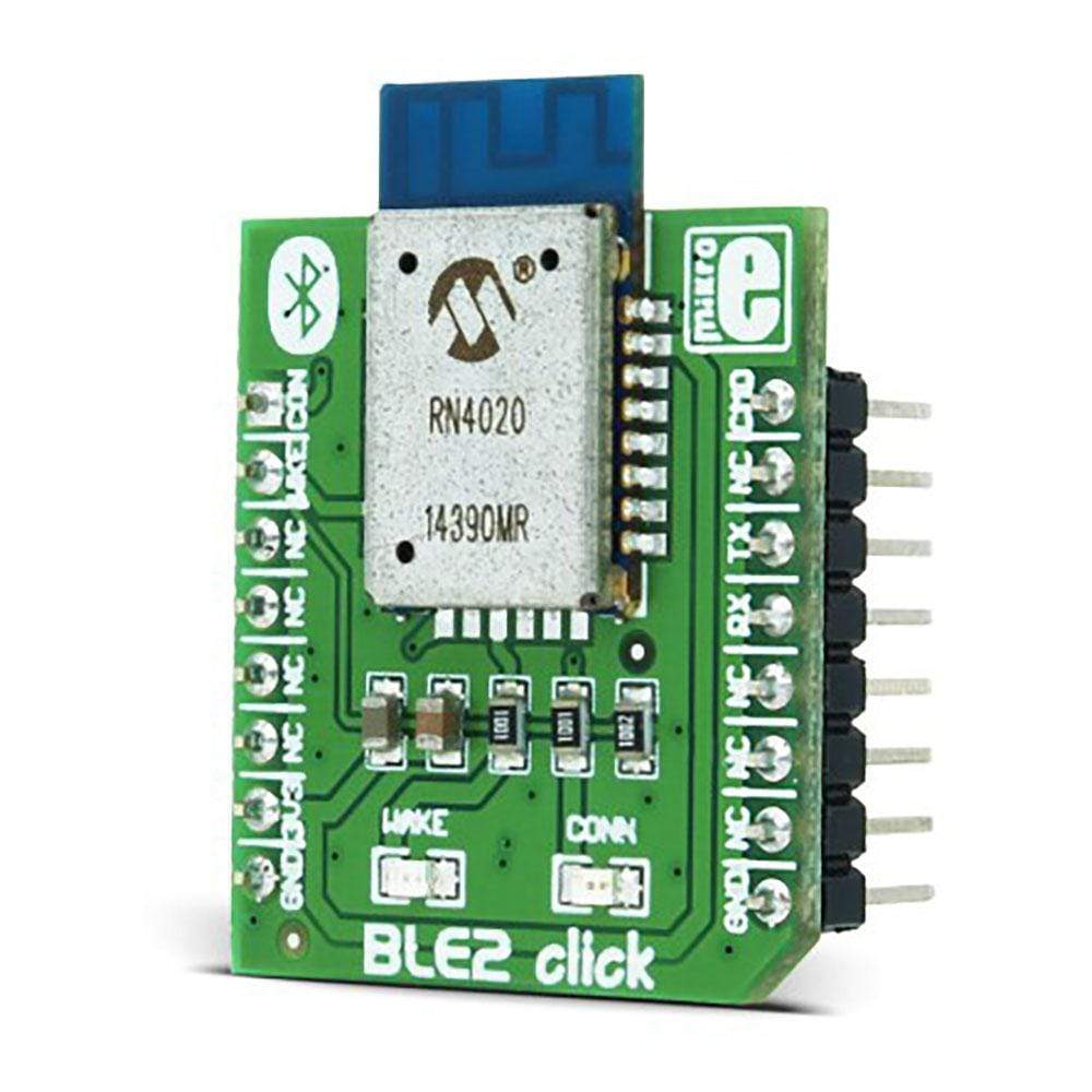
Le BLE 2 Click Board™ est un excellent choix si vous souhaitez une connectivité simple et temporaire avec vos appareils intelligents via Bluetooth 4.1.
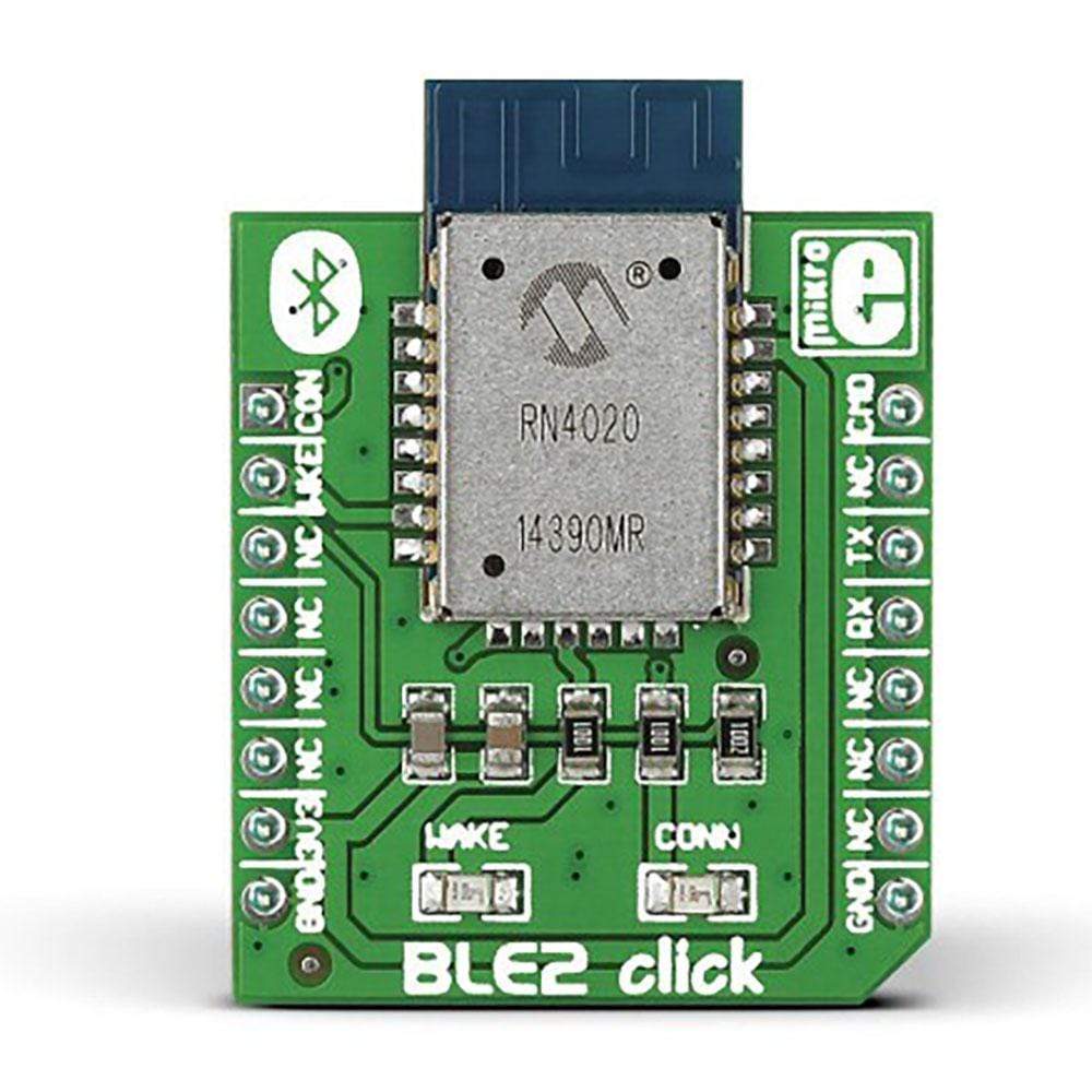
La carte BLE 2 Click Board™ est dotée du module RN4020 de Microchip, qui intègre la RF, un contrôleur de bande de base et un processeur API de commande, ce qui en fait une solution Bluetooth Low Energy complète. La carte Click Board™ communique avec le microcontrôleur de la carte cible via les lignes MikroBUSRX, TX et AN (CMD), PWM (con.) et RST (réveil). La carte est conçue pour utiliser uniquement une alimentation 3,3 V.
The BLE2 Click Board™ is an excellent choice if you want simple, temporary connectivity with your smart devices over Bluetooth 4.1.
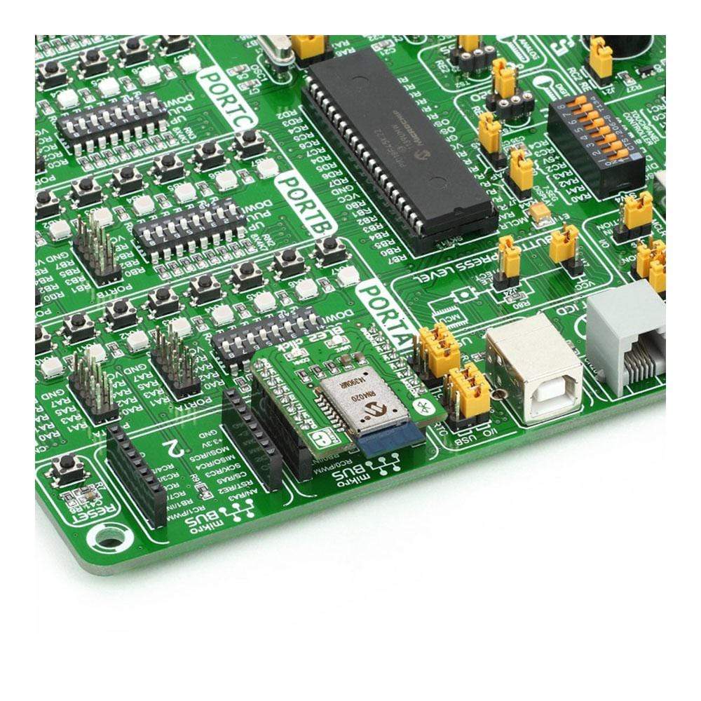
The BLE2 Click Board™ features the RN4020 module from Microchip, which integrates RF, a baseband controller, and a command API processor, making it a complete Bluetooth Low Energy solution. The click communicates with the target board MCU through mikroBUS™ RX, TX and AN (CMD), PWM (con.), and RST (wake) lines. The board is designed to use a 3.3V power supply only.
Microchip Low-energy Data Profile
The RN4020 has Microchip's Low-energy Data Profile (MLDP) which enables an asynchronous serial data connection between two RN4020 devices (which could be two BLE2 Click Board™s). The module can be remotely controlled or updated over the air by another module over a secure connection or can be controlled or updated through its UART interface.
PCB trace Antenna
The RN4020 module aboard BLE2 click incorporates a PCB antenna with a range of at least 30m.
Bluetooth 4.1
Bluetooth 4.1 is intended for IoT, it has low power consumption and lets any device be a peripheral and a hub at the same time.
Specifications
Type | BT/BLE |
Applications | Bluetooth Low Energy is becoming a pervasive standard for IoT applications in any number of domains (home automation, fitness, health and so on). Because of MLDP support, BLE2 click works great in pairs |
On-board modules | Microchip RN4020 |
Key Features | N4020 Bluetooth 4.1 module. PCB antenna. Integrated TCP/IP stack |
Interface | GPIO, UART |
Compatibility | mikroBUS |
Click board size | S (28.6 x 25.4 mm) |
Input Voltage | 3.3V |
Pinout diagram
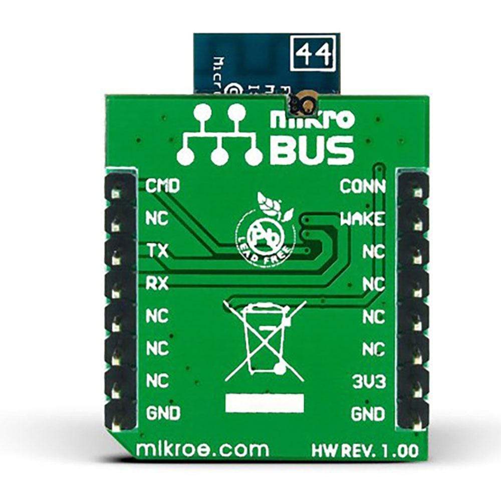
This table shows how the pinout on the BLE2 Click Board™ corresponds to the pinout on the mikroBUS™ socket (the latter shown in the two middle columns).
Notes | Pin | Pin | Notes | ||||
---|---|---|---|---|---|---|---|
Indicates connection state | CONN | 1 | AN | PWM | 16 | CMD/MLDP | Command or MLDP mode |
Deep Sleep Wake | SWAKE | 2 | RST | INT | 15 | NC | |
NC | 3 | CS | TX | 14 | BT_UART_TX | UART Transmit | |
NC | 4 | SCK | RX | 13 | BT_UART_RX | UART Receive | |
NC | 5 | MISO | SCL | 12 | NC | ||
NC | 6 | MOSI | SDA | 11 | NC | ||
Power supply | +3.3V | 7 | 3.3V | 5V | 10 | NC | |
Ground | GND | 8 | GND | GND | 9 | GND | Ground |
The code sets up the BLE2 Click Board™ and sends messages through Bluetooth low energy every 5 seconds. If the BLE2 click board receives messages over Bluetooth low energy, the code displays the message and updates the buffer.
01 void main() { 02 Display_Init(); 03 MCU_Init(); 04 #ifdef INIT_BLE 05 BLE_Init(); 06 delay_ms(2000); 07 #else 08 RN_WAKE = 1; 09 wait_response("CMD"); 10 #endif 11 DrawFrame(); 12 InitTimer2(); 13 while(1) 14 { 15 if(data_ready) 16 { 17 //If characteristic is configured as write 18 //received messages come here 19 Display_Message(); 20 reset_buff(); 21 } 22 else 23 { 24 //Test: every 5sec increase baterry level (0 to 100%) 25 //and send value via Bluetooth Low Energy 26 if (tmr_flg) 27 { 28 batt_level++; 29 if(batt_level > 100) 30 { 31 batt_level = 0; 32 } 33 Display_BatteryLevel(); 34 if(RN_CONN) 35 { //send battery level value if BLE connected 36 shorttohex(batt_level, batt_level_txt); 37 ltrim(batt_level_txt); 38 ble2_write_server_characteristic_value_via_UUID("2A19",batt_level_txt); 39 } 40 tmr_flg = 0; 41 } 42 } 43 } 44 }
Frequently Asked Questions
Have a Question?
Be the first to ask a question about this.